BRAKE CONTROL / DYNAMIC CONTROL SYSTEMS ELECTRONICALLY CONTROLLED BRAKE SYSTEM(for Gasoline Model) Steering Angle Sensor Wrong Installation (X0455)
DESCRIPTION
| Code | Tester Display | Measurement Item | Trouble Area |
|---|---|---|---|
| X0455 | Steering Angle Sensor Wrong Installation | History of steering angle sensor being installed incorrectly | ·
Correct spiral cable with sensor sub-assembly ·
Steering angle sensor |
CAUTION / NOTICE / HINT
- NOTICE:
-
After performing the inspection, check and clear the vehicle control history (RoB).
PROCEDURE
Perform the Health Check using the GTS.
- Result:
Result Proceed to DTCs are not output A DTCs are output B
A
B
- Result:
Proceed to NEXT
NEXT
Check Data List item "steering angle signal information".
- Chassis > Steering Angle Sensor > Data List
-
Tester Display Measurement Item Range Normal Condition Diagnostic Note Steering Angle Signal Information Steering angle value (Rotation to the left side is positive) Min.: -3072.0°
Max.: 3070.5°Turning left: 0.0 to 3070.5°
Turning right: -3072.0 to 0.0°During steering operation: Changes in proportion with steering wheel rotation
- Chassis > Steering Angle Sensor > Data List
-
Tester Display Steering Angle Signal Information - 50003 445 31
Save the steering angle signal information to the GTS memory.
- NOTICE:
- ·
If the value is +/- 360° (+/-15°), the steering angle sensor was incorrectly installed by 1 rotation.
·If the value is +/- 720° (+/-15°), the steering angle sensor was incorrectly installed by 2 rotations.
·In situations other than the above, the steering angle sensor may have been incorrectly installed by 3 or more rotations.
In this case, it is possible that the proper installation or removal procedures were not followed, and the steering angle sensor may have been damaged.
- Result:
Result Proceed to 0 +/- 15° A +/- 360° (+/-15°) or +/- 720° (+/-15°) B None of the above conditions are met C
A
B
C
Using the GTS, clear the Vehicle Control History (RoB).
- Chassis > Brake/EPB > Utility
-
Tester Display Vehicle Control History (RoB) - 50005 435 55
- Result:
Proceed to NEXT
NEXT
Disconnect cable from negative (-) battery terminal.
- HINT:
-
If the cable is not disconnected from the negative (-) battery terminal, it may not be possible to obtain an accurate steering angle sensor zero point.
Connect cable to negative (-) battery terminal.
Drive the vehicle straight ahead at 35 km/h (22 mph) or more for at least 5 seconds.
- Result:
Proceed to NEXT
NEXT
Perform a road test under the same malfunction conditions recreated based on the Freeze Frame Data or customer problem analysis.
Using the GTS, check for Vehicle Control History (RoB).
- Chassis > Brake/EPB > Utility
-
Tester Display Vehicle Control History (RoB) - 50005 435 55
- Result:
Result Proceed to X0455 is not output A X0455 is output B
A
B
Remove the spiral cable with sensor sub-assembly.
- NOTICE:
- ·
Be sure to disconnect the cable from the negative (-) battery terminal before removing the spiral cable with sensor sub-assembly.
- HINT:
-
If the cable is not disconnected from the negative (-) battery terminal, it may not be possible to obtain an accurate steering angle sensor zero point.
·Do not disconnect the steering angle sensor from the spiral cable.
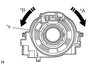
| *A | Clockwise |
| *B | Counterclockwise |
| *a | Interlock |
Based on the steering angle signal information that was saved to the GTS memory earlier, rotate the spiral cable with sensor sub-assembly.
- NOTICE:
- ·
Rotate the steering angle sensor without disconnecting it from the spiral cable.
·Make sure to follow the adjustment method shown in the table.
·Failure to observe the following precautions may result in damage to the spiral cable with sensor sub-assembly.
-When rotating the spiral cable with sensor sub-assembly, make sure to push on the interlock to release the interlock.
-Do not turn the spiral cable with sensor sub-assembly using the airbag wire harness.
-Do not forcibly rotate the part.
-Make sure to perform the correct number of rotations in the correct direction.
| Steering Angle Signal Information | Correction Method |
|---|---|
| 360° (+/-15°) | Rotate clockwise (to the right), 1 rotation. |
| - 360° (+/-15°) | Rotate counterclockwise (to the left), 1 rotation. |
| 720° (+/-15°) | Rotate clockwise (to the right), 2 rotations. |
| - 720° (+/-15°) | Rotate counterclockwise (to the left), 2 rotations. |
Install the spiral cable with sensor sub-assembly.
- Result:
Proceed to NEXT
NEXT
- Result:
Proceed to NEXT
NEXT
Check Data List item "steering angle signal information".
- Chassis > Steering Angle Sensor > Data List
-
Tester Display Measurement Item Range Normal Condition Diagnostic Note Steering Angle Signal Information Steering angle value
(Rotation to the left side is positive)Min.: -3072.0°
Max.: 3070.5°Turning left: 0.0 to 3070.5°
Turning right: -3072.0 to 0.0°During steering operation: Changes in proportion with steering wheel rotation
- Chassis > Steering Angle Sensor > Data List
-
Tester Display Steering Angle Signal Information - 50003 445 31
- Result:
Result Proceed to 0 +/- 15° A None of the above conditions are met B
A
B
Using the GTS, clear the Vehicle Control History (RoB).
- Chassis > Brake/EPB > Utility
-
Tester Display Vehicle Control History (RoB) - 50005 435 55
- Result:
Proceed to NEXT
NEXT
Drive the vehicle straight ahead at 35 km/h (22 mph) or more for at least 5 seconds.
- Result:
Proceed to NEXT
NEXT
Perform a road test under the same malfunction conditions recreated based on the Freeze Frame Data or customer problem analysis.
Using the GTS, check for Vehicle Control History (RoB).
- Chassis > Brake/EPB > Utility
-
Tester Display Vehicle Control History (RoB) - 50005 435 55
- Result:
Result Proceed to X0455 is not output A X0455 is output B
A
B
Perform steering wheel assembly center position adjustment.
- Result:
Proceed to NEXT
NEXT
for front wheel alignment: Click hereGeneral>MAINTENANCE>FRONT WHEEL ALIGNMENT>ADJUSTMENT202111,999999,_V1,_112220,_0509017,RM1000000020321,
for rear wheel alignment: Click hereGeneral>MAINTENANCE>REAR WHEEL ALIGNMENT>ADJUSTMENT202111,999999,_V1,_112220,_0509018,RM1000000020322,
- Result:
Proceed to NEXT
NEXT
Using the GTS, clear the Vehicle Control History (RoB).
- Chassis > Brake/EPB > Utility
-
Tester Display Vehicle Control History (RoB) - 50005 435 55
- Result:
Proceed to NEXT
NEXT
Disconnect cable from negative (-) battery terminal.
- HINT:
-
If the cable is not disconnected from the negative (-) battery terminal, it may not be possible to obtain an accurate steering sensor zero point.
Connect cable to negative (-) battery terminal.
Drive the vehicle straight ahead at 35 km/h (22 mph) or more for at least 5 seconds.
- Result:
Proceed to NEXT
NEXT
Perform a road test under the same malfunction conditions recreated based on the Freeze Frame Data or customer problem analysis.
Using the GTS, check for Vehicle Control History (RoB).
- Chassis > Brake/EPB > Utility
-
Tester Display Vehicle Control History (RoB) - 50005 435 55
- Result:
Result Proceed to X0455 is not output A X0455 is output B
A
B