M20D-FKS ENGINE MECHANICAL ENGINE UNIT REMOVAL
CAUTION / NOTICE / HINT
The necessary procedures (adjustment, calibration, initialization, or registration) that must be performed after parts are removed and installed, or replaced during engine unit removal/installation are shown below.
| Replaced Part or Performed Procedure | Necessary Procedure | Effect/Inoperative Function when Necessary Procedure not Performed | Link |
|---|---|---|---|
| Replacement of ECM | Perform Vehicle Identification Number (VIN) or frame number registration | DTC P063051 is output | ( 202304,999999,_51,_083058,_0401834,RM1000000029C6T,) 202304,999999,_51,_083058,_0401834,RM1000000029C6T,)
|
| Perform Total Short Trip Estimate Registration | - | ||
GPF Deposition Values:
·
GPF deposition values save ·
GPF deposition values write |
·
MIL comes on ·
Deterioration of fuel efficiency |
||
| Update ECU security key | Vehicle Control History (RoB) are stored | (202405,999999,_V1,_083041,_0402305,RM100000002ISNL,)
|
|
| ECU communication ID registration | Engine start function | See Service Bulletin for the registration method. | |
for K121:
If transaxle compensation code read from ECM -
Transfer transaxle compensation code -
Deceleration sensor zero point calibration -
CVT oil pressure calibration -
Perform road test to allow ECM to learn |
·
Large shift shock ·
Deterioration of fuel efficiency |
for Initialization:
( 202409,999999,_52,_138176,_0584691,RM100000002NRHB,)
for Registration: ( 202304,999999,_52,_138176,_0584691,RM1000000029HF6,)
|
|
for K121:
If transaxle compensation code not read from ECM -
Reset transaxle compensation code -
Deceleration sensor zero point calibration -
CVT oil pressure calibration -
Perform road test to allow ECM to learn |
|||
for K121F:
If transaxle compensation code read from ECM -
Transfer transaxle compensation code -
Deceleration sensor zero point calibration -
CVT oil pressure calibration -
Perform road test to allow ECM to learn |
·
Large shift shock ·
Deterioration of fuel efficiency |
for Initialization:
( 202409,999999,_52,_138817,_0596468,RM100000002NRBH,)
for Registration: ( 202304,999999,_52,_138817,_0596468,RM100000002AWR8,)
|
|
for K121F:
If transaxle compensation code not read from ECM -
Reset transaxle compensation code -
Deceleration sensor zero point calibration -
CVT oil pressure calibration -
Perform road test to allow ECM to learn |
|||
| Exhaust manifold | Reset total short trip estimate | ·
MIL comes on ·
Deterioration of fuel efficiency |
(202409,999999,_51,_083058,_0401834,RM100000002NA8M,)
|
| Replacement of front exhaust pipe assembly | GPF deposition value clear | ·
MIL comes on ·
Deterioration of fuel efficiency |
(202409,999999,_51,_083058,_0401834,RM100000002NA8M,)
|
·
Throttle body with motor assembly ·
Cam timing control motor with EDU assembly (Including removal and installation) ·
Camshaft timing gear assembly (Including removal and installation) ·
Cylinder head sub-assembly ·
Camshaft (for intake or exhaust camshaft) ·
Camshaft timing exhaust gear assembly ·
Piston or piston ring ·
Mass air flow meter sub-assembly ·
Port fuel injector assembly ·
Direct fuel injector assembly ·
Fuel pump (for low pressure side) ·
Fuel pump assembly (for high pressure side) ·
Fuel pressure sensor (for low pressure side) ·
Fuel pressure sensor (for high pressure side) ·
Air fuel ratio sensor (sensor 1) ·
Air fuel ratio sensor (sensor 2) ·
Engine coolant temperature sensor ·
Spark plug ·
Ignition coil assembly ·
EGR valve assembly ·
Air intake system parts ·
Gas leaks from exhaust system ·
Knock control sensor |
Inspection after repair | ·
Poor idle, etc. ·
Engine start function, etc. |
(202409,999999,_51,_083058,_0401834,RM100000002NA8M,)
|
for K121:
Replacement of continuously variable transaxle assembly |
Air bleed oil pump with motor assembly | Stop and start system | (202409,999999,_51,_083056,_0402418,RM100000002NSFT,)
|
·
Input transaxle compensation code into ECM ·
Perform reset memory ·
Deceleration sensor zero point calibration ·
CVT oil pressure calibration ·
Perform road test to allow ECM to learn |
·
Large shift shock ·
Deterioration of fuel efficiency |
for Initialization:
( 202409,999999,_52,_138176,_0584691,RM100000002NRHB,)
for Registration: ( 202304,999999,_52,_138176,_0584691,RM1000000029HF6,)
|
|
for K121F:
Replacement of continuously variable transaxle assembly |
Air bleed oil pump with motor assembly | Stop and start system | (202409,999999,_51,_083056,_0402418,RM100000002NSFT,)
|
·
Input transaxle compensation code into ECM ·
Perform reset memory ·
Deceleration sensor zero point calibration ·
CVT oil pressure calibration ·
Perform road test to allow ECM to learn |
·
Large shift shock ·
Deterioration of fuel efficiency |
for Initialization:
( 202409,999999,_52,_138817,_0596468,RM100000002NRBH,)
for Registration: ( 202304,999999,_52,_138817,_0596468,RM100000002AWR8,)
|
|
| CVT fluid | ATF thermal degradation estimate reset | The value of the Data List item "ATF Thermal Degradation Estimate" is not estimated correctly | for K121:
( 202409,999999,_52,_138176,_0584691,RM100000002NRHB,)
for K121F: ( 202409,999999,_52,_138817,_0596468,RM100000002NRBH,)
|
| Air bleed oil pump with motor assembly | Stop and start system | (202409,999999,_51,_083056,_0402418,RM100000002NSFT,)
|
|
| Front bumper assembly (Including removal and installation) | Front television camera view adjustment | Panoramic view monitor system | (202304,999999,_56,_083082,_0586733,RM1000000029R9F,)
|
| Suspension, tires, etc. | Parking assist ECU initialization | Panoramic view monitor system | (202304,999999,_56,_083082,_0586733,RM1000000029R9F,)
|
| Front wheel alignment adjustment | 1.
Perform "Reset Memory". 2.
Perform acceleration sensor zero point calibration and store system information memorization. |
·
VSC is disabled or malfunctions ·
DTCs are output ·
Slip indicator light illuminates ·
ABS warning light illuminates |
(202304,999999,_54,_083077,_0402316,RM100000002AG8P,)
|
- HINT:
-
When the cable is disconnected / reconnected to the auxiliary battery terminal, systems temporarily stop operating. However, each system has a function that completes learning the first time the system is used.
- ·
Learning completes when vehicle is driven
Effect/Inoperative Function When Necessary Procedures are not Performed Necessary Procedures Link Stop and start system Drive the vehicle until stop and start control is permitted (approximately 5 to 60 minutes). ( 202409,999999,_51,_083056,_0402418,RM100000002NSFO,)
Lane tracing assist system Drive the vehicle straight ahead at 15 km/h (10 mph) or more for 1 second or more. ( 201910,999999,_58,_083101,_0401880,RM100000001JE9I,)
Pre-collision system
·Learning completes when vehicle is operated normally
Effect/Inoperative Function When Necessary Procedures are not Performed Necessary Procedures Link *: w/ Power back door system
Power back door function* Fully close the back door by hand.
- HINT:
-
Initialization is not necessary if the above procedures are performed while the back door is closed.
( 202304,999999,_59,_083093,_0584672,RM1000000029PGT,)
Power door lock control system If the back door is locked and therefore cannot be opened, it is necessary to unlock the back door using the door control switch, electrical key transmitter sub-assembly switch. ( 202409,999999,_58,_083092,_0403003,RM100000002NS90,)
Air conditioning system After the ignition switch is turned to ON, the servo motor standard position is recognized -
- NOTICE:
-
This procedure includes the removal of small-head bolts. Refer to Small-Head Bolts of Basic Repair Hint to identify the small-head bolts.
PROCEDURE

 43457
1.REMOVE DRIVE SHAFT BEARING BRACKET
43457
1.REMOVE DRIVE SHAFT BEARING BRACKET
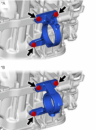
| *A | for 2WD |
| *B | for AWD |
Remove the 3 bolts and drive shaft bearing bracket.
16361A
2.REMOVE V-RIBBED BELT
27020
3.REMOVE GENERATOR ASSEMBLY
88310
4.REMOVE COMPRESSOR WITH PULLEY ASSEMBLY
16620D
5.REMOVE V-RIBBED BELT TENSIONER ASSEMBLY
- NOTICE:
-
- ·
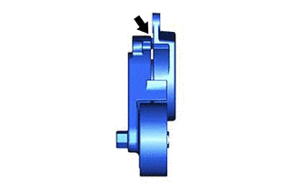
Do not apply or add any oil or grease to the belt tensioner to prevent abnormal noises from the belt tensioner pulley, belt squealing, etc.
·Do not allow oil or grease to adhere to the moving parts of the belt tensioner, as this may cause malfunctions.
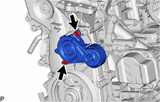
Remove the 2 bolts and V-ribbed belt tensioner assembly from the No. 2 timing chain cover assembly.
16572D
6.DISCONNECT NO. 2 RADIATOR HOSE
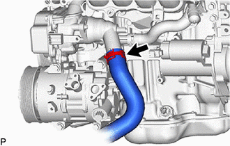
Slide the clip and disconnect the No. 2 radiator hose from the water inlet.
16207
7.REMOVE NO. 2 WATER BY-PASS PIPE SUB-ASSEMBLY
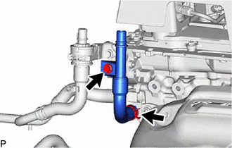
Slide the clip and disconnect the No. 2 water by-pass pipe sub-assembly from the outlet water by-pass sub-assembly.
Remove the bolt and No. 2 water by-pass pipe sub-assembly from the water hose clamp bracket.
16260
8.REMOVE FLOW SHUTTING VALVE (WATER BY-PASS HOSE ASSEMBLY)
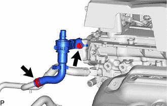
Remove the bolt to disconnect the flow shutting valve (water by-pass hose assembly) from the water hose clamp bracket.
Slide the clip and disconnect the flow shutting valve (water by-pass hose assembly) from the No. 1 water by-pass pipe sub-assembly.
- HINT:
-
Use a container to catch any engine coolant which flows out of the flow shutting valve (water by-pass hose assembly) and outlet water by-pass sub-assembly.
9.REMOVE WATER HOSE CLAMP BRACKET
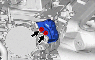
Remove the 2 bolts and water hose clamp bracket.
22030
10.REMOVE THROTTLE BODY WITH MOTOR ASSEMBLY
25680
11.REMOVE EGR COOLER ASSEMBLY
25601
12.REMOVE NO. 1 EGR PIPE SUB-ASSEMBLY
25620
13.REMOVE EGR VALVE ASSEMBLY
16279
14.REMOVE NO. 3 WATER BY-PASS PIPE
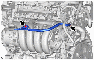
Remove the bolt and No. 3 water by-pass pipe from the intake manifold.
Slide the clip and disconnect the No. 3 water by-pass pipe from the water outlet.
17138B
15.REMOVE INTAKE MANIFOLD STAY
17111
16.REMOVE INTAKE MANIFOLD
17177
17.REMOVE NO. 1 INTAKE MANIFOLD TO HEAD GASKET
23910A
18.DISCONNECT FUEL TUBE SUB-ASSEMBLY
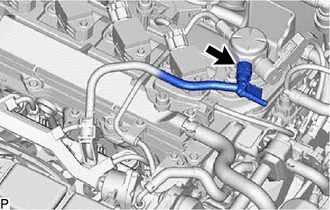
Remove the fuel tube sub-assembly from the fuel pump assembly.
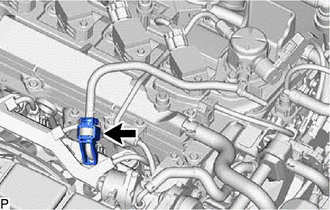
Remove the fuel pipe clamp from the fuel tube connector.
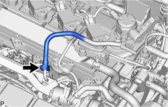
Remove the fuel tube sub-assembly from the fuel delivery pipe with sensor assembly.
23801P
19.REMOVE NO. 1 FUEL PIPE SUB-ASSEMBLY
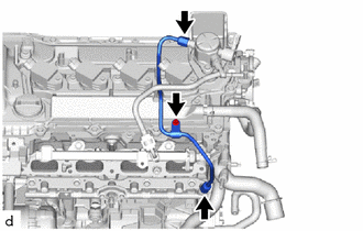
Remove the bolt.
Using a 17 mm union nut wrench, loosen the 2 union nuts of the No. 1 fuel pipe sub-assembly.
23100X
20.REMOVE FUEL (ENGINE ROOM SIDE) PUMP ASSEMBLY (for High Pressure)
16260
21.REMOVE WATER BY-PASS HOSE ASSEMBLY
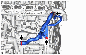
Remove the bolt.
Slide the 2 clips and remove the water by-pass hose assembly from the water inlet with thermostat sub-assembly and cylinder head sub-assembly.
82219A
22.REMOVE SENSOR WIRE
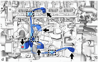
Disconnect the 4 connectors.
Detach the 3 clamps.
Remove the bolt and sensor wire from the water inlet with thermostat sub-assembly.
82126A
23.REMOVE NO. 6 ENGINE WIRE
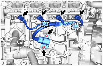
Disconnect the 4 connectors.
Detach the 2 clamps.
Remove the 2 nuts and No. 6 engine wire from the wire harness clamp bracket.
23807
24.REMOVE FUEL DELIVERY PIPE SUB-ASSEMBLY
23891
25.REMOVE FUEL DELIVERY SPACER
23291
26.REMOVE INJECTOR VIBRATION INSULATOR
82125N
27.REMOVE NO. 5 ENGINE WIRE
23250F
28.REMOVE PORT FUEL INJECTOR ASSEMBLY
23814B
29.REMOVE FUEL DELIVERY PIPE
23250E
30.REMOVE DIRECT FUEL INJECTOR ASSEMBLY
23255A
31.REMOVE FUEL INJECTOR SEAL
19500
32.REMOVE IGNITION COIL ASSEMBLY
11452D
33.REMOVE ENGINE OIL LEVEL DIPSTICK GUIDE
Remove the engine oil level dipstick.
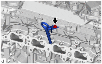
Remove the bolt and engine oil level dipstick guide from the cylinder head sub-assembly.
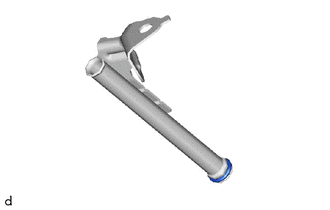
Remove the O-ring from the engine oil level dipstick guide.
16031
34.REMOVE WATER INLET WITH THERMOSTAT SUB-ASSEMBLY
16032
35.REMOVE ENGINE WATER PUMP ASSEMBLY (WATER INLET HOUSING)
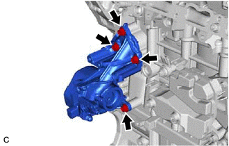
Remove the 4 bolts, engine water pump assembly (water inlet housing) and gasket from the cylinder block sub-assembly.
17169A
36.REMOVE NO. 3 EXHAUST MANIFOLD HEAT INSULATOR
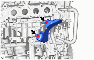
Remove the 2 bolts and No. 3 exhaust manifold heat insulator from the cylinder block sub-assembly.
37.REMOVE PURGE VALVE (PURGE VSV)
25759A
38.REMOVE VACUUM SURGE TANK BRACKET
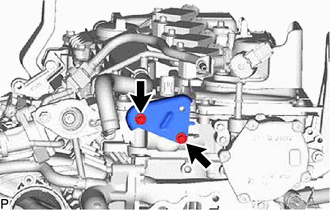
Remove the 2 bolts and vacuum surge tank bracket from the camshaft housing sub-assembly.
39.REMOVE NO. 2 PCV HOSE
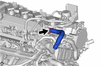
Slide the hose clip and remove the No. 2 PCV hose from the cylinder head cover sub-assembly.
40.REMOVE WIRE HARNESS CLAMP BRACKET
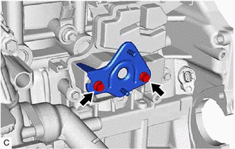
Remove the 2 bolts and wire harness clamp bracket from the No. 1 ventilation case.
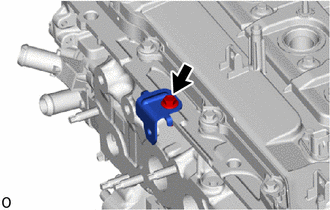
Remove the bolt and wire harness clamp bracket from the camshaft housing sub-assembly.
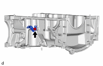
Remove the bolt and wire harness clamp bracket from the stiffening crankcase assembly.