RM3660EC _95 ADAS / AD _139716 ADVANCED DRIVER ASSISTANCE SYSTEM _0601172 LANE TRACING ASSIST SYSTEM(for NR Series Engine) J

ADVANCED DRIVER ASSISTANCE SYSTEM  LANE TRACING ASSIST SYSTEM(for NR Series Engine)  Steering Pad Switch Circuit  


DESCRIPTION

The forward recognition camera receives LTA main switch signals from the steering pad switch assembly.

WIRING DIAGRAM
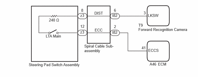
A527574E15
1.771,0.646 2.385,0.844 0.615,0.198 10 false 240 Ω 1.656,1.229 2.365,1.448 0.708,0.219 10 false LTA Main 1.042,2.271 3.167,2.5 2.125,0.229 10 false Steering Pad Switch Assembly 3.052,1.594 4.156,2.021 1.104,0.427 10 false Spiral Cable Sub-assembly 5.01,0.99 6.865,1.208 1.854,0.219 10 false Forward Recognition Camera 5.01,0.833 5.469,1.031 0.458,0.198 10 false T9 2.906,0.479 3.219,0.677 0.313,0.198 10 false z3 2.906,1.083 3.146,1.26 0.24,0.177 10 false z3 2.938,0.292 3.094,0.49 0.156,0.198 10 false 8 2.906,0.875 3.135,1.073 0.229,0.198 10 false 12 3.417,0.396 4.031,0.594 0.615,0.198 10 false DIST 3.427,1.01 3.885,1.208 0.458,0.198 10 false ECC 4.063,0.479 4.313,0.677 0.25,0.198 10 false I82 4.063,1.094 4.292,1.292 0.229,0.198 10 false I82 4.125,0.292 4.292,0.5 0.167,0.208 10 false 6 4.125,0.885 4.281,1.063 0.156,0.177 10 false 2 5.198,0.385 5.354,0.583 0.156,0.198 10 false 3 5.354,0.479 5.833,0.667 0.479,0.188 10 false LKSW 5.417,2.25 5.729,2.438 0.313,0.188 10 false A46 5.719,2.25 6.063,2.438 0.344,0.188 10 false ECM 5.365,1.75 5.823,1.948 0.458,0.198 10 false ECCS 5.125,1.656 5.583,1.854 0.458,0.198 10 false 41

CAUTION / NOTICE / HINT

NOTICE:

The vehicle is equipped with a Supplemental Restraint System (SRS) which includes components such as airbags. Before servicing (including removal or installation of parts), be sure to read the precaution for Supplemental Restraint System.

Click hereVehicle Interior>SUPPLEMENTAL RESTRAINT SYSTEMS>AIRBAG SYSTEM (for NR Series Engine)>PRECAUTION


PROCEDURE

1.INSPECT STEERING PAD SWITCH ASSEMBLY

OK

2.INSPECT SPIRAL CABLE SUB-ASSEMBLY

NG

2.INSPECT SPIRAL CABLE SUB-ASSEMBLY

OK

3.CHECK HARNESS AND CONNECTOR (SPIRAL CABLE SUB-ASSEMBLY - FORWARD RECOGNITION CAMERA)

NG

3.CHECK HARNESS AND CONNECTOR (SPIRAL CABLE SUB-ASSEMBLY - FORWARD RECOGNITION CAMERA)
a.

Disconnect the I82 spiral cable sub-assembly connector.


b.

Disconnect the T9 forward recognition camera connector.


c.

Measure the resistance according to the value(s) in the table below.

Standard Resistance:
Tester Connection Condition Specified Condition
I82-6 (DIST) - T9-3 (LKSW) Always Below 1 Ω
I82-6 (DIST) or T9-3 (LKSW) - Body ground Always 10 kΩ or higher


d.

Connect the T9 forward recognition camera connector.


e.

Connect the I82 spiral cable sub-assembly connector.


Result:
Proceed to
OK
NG


OK

4.CHECK HARNESS AND CONNECTOR (SPIRAL CABLE SUB-ASSEMBLY - ECM)

NG

REPAIR OR REPLACE HARNESS OR CONNECTOR

4.CHECK HARNESS AND CONNECTOR (SPIRAL CABLE SUB-ASSEMBLY - ECM)
a.

Disconnect the A46 ECM connector.


b.

Measure the resistance according to the value(s) in the table below.

Standard Resistance:
Tester Connection Condition Specified Condition
I82-2 (ECC) - A46-41 (ECCS) Always Below 1 Ω
I82-2 (ECC) or A46-41 (ECCS) - Body ground Always 10 kΩ or higher


Result:
Proceed to
OK
NG


OK

NG

REPAIR OR REPLACE HARNESS OR CONNECTOR