WINDOW / GLASS WINDSHIELD GLASS INSTALLATION
CAUTION / NOTICE / HINT
- NOTICE:
-
When replacing the windshield glass of a vehicle equipped with a forward recognition camera, make sure to use a Toyota genuine part. If a non-Toyota genuine part is used, the forward recognition camera may not be able to be installed due to a missing bracket. Also, the dynamic radar cruise control system, lane departure alert system, pre-collision system, forward recognition camera system or automatic high beam system may not operate properly due to a difference in the transmissivity or black ceramic border.
PROCEDURE

 1.INSTALL NO. 1 WINDSHIELD GLASS STOPPER (for 2-piece Type)
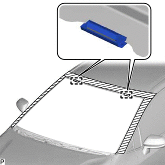
Install 2 new No. 1 windshield glass stoppers to the vehicle body as shown in the illustration.
- HINT:
-
Only 2-piece type windshield glass stoppers are provided as supply parts. Use 2-piece type stoppers as replacements even if 1-piece type stoppers were originally installed.
2.INSTALL NO. 2 WINDSHIELD GLASS STOPPER (for 2-piece Type)
Using a brush or sponge, coat the installation area of 2 new No. 2 windshield glass stoppers with glass primer.
- NOTICE:
- ·
Do not apply too much glass primer.
·Allow the glass primer to dry for 3 minutes or more.
·Throw away any leftover glass primer.
- HINT:
-
If an area other than specified is coated by accident, wipe off the glass primer with a clean piece of cloth before it dries.
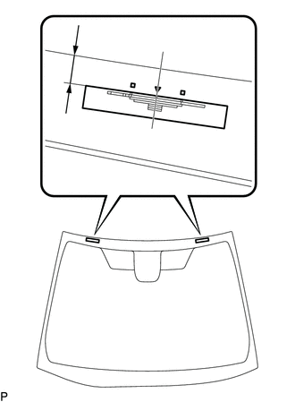
| *A | Back Side |
| *a | Ceramic Notch |
| *b | Windshield Glass Edge Side |
Install the 2 new No. 2 windshield glass stoppers to the windshield glass as shown in the illustration.
- Standard Dimension:
Area Dimension a 13.6 to 14.6 mm (0.535 to 0.575 in.)
- HINT:
-
Only 2-piece type windshield glass stoppers are provided as supply parts. Use 2-piece type stoppers as replacements even if 1-piece type stoppers were originally installed.
3.INSTALL WINDSHIELD OUTSIDE MOULDING
Using a brush or sponge, coat the installation area of a new windshield outside moulding with glass primer.
- NOTICE:
- ·
Do not apply too much glass primer.
·Allow the glass primer to dry for 3 minutes or more.
·Throw away any leftover glass primer.
- HINT:
-
If an area other than specified is coated by accident, wipe off the glass primer with a clean piece of cloth before it dries.
Install the new windshield outside moulding to the windshield glass as shown in the illustration.
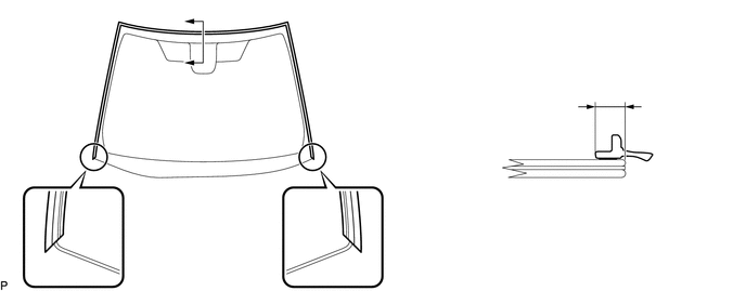
| *A | Back Side | - | - |
| *a | Edge Of Curved Surface | - | - |
- Standard Dimension:
Area Dimension a 6.5 mm (0.256 in.)
56117A
4.INSTALL WINDOW GLASS ADHESIVE DAM
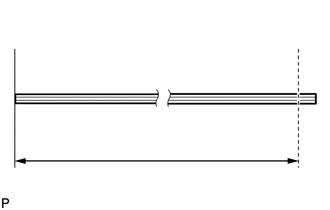
| *a | Cut |
Cut a new window glass adhesive dam so that it is the appropriate size as shown in the illustration.
- Standard Dimension:
Area Dimension a 129.6 to 130.0 cm (4.25 to 4.26 ft.)
Using a brush or sponge, coat the installation area of the new window glass adhesive dam with glass primer.
- NOTICE:
- ·
Do not apply too much glass primer.
·Allow the glass primer to dry for 3 minutes or more.
·Throw away any leftover glass primer.
- HINT:
-
If an area other than specified is coated by accident, wipe off the glass primer with a clean piece of cloth before it dries.
Install the window glass adhesive dam to the windshield glass as shown in the illustration.
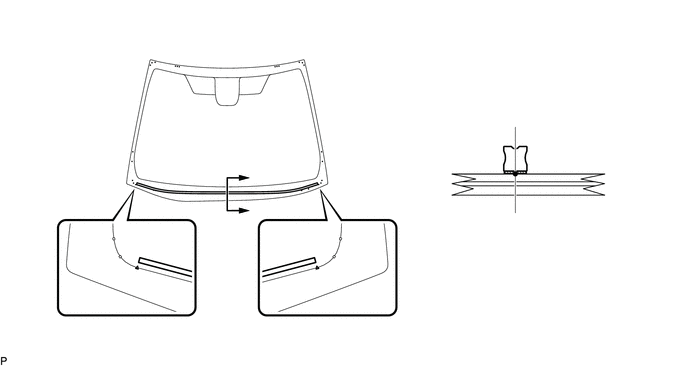
| *A | Back Side | - | - |
| *a | Ceramic Notch | *b | Window Glass Adhesive Dam Positioning Center |
56153C
5.INSTALL FRONT WINDOW INNER CENTER MOULDING
- HINT:
-
Perform the following procedure only when replacement of a front window inner center moulding is necessary.
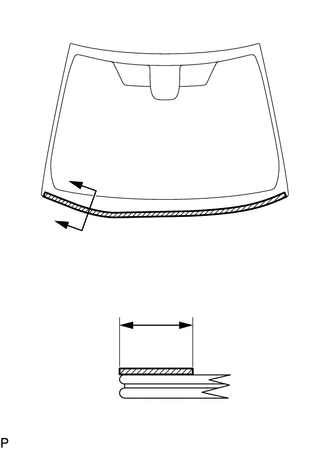
| *A | Back Side |

|
Glass Primer |
Using a brush or sponge, coat the installation area of a new front window inner center moulding with glass primer.
- Standard Dimension:
Area Dimension a 17.5 to 20.5 mm (0.689 to 0.807 in.)
- NOTICE:
- ·
Do not apply too much glass primer.
·Allow the glass primer to dry for 3 minutes or more.
·Throw away any leftover glass primer.
- HINT:
-
If an area other than specified is coated by accident, wipe off the glass primer with a clean piece of cloth before it dries.
Install the new front window inner center moulding to the windshield glass as shown in the illustration.
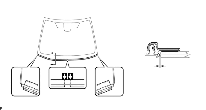
| *A | Back Side | - | - |
| *a | Matchmark | *b | Edge Of Curved Surface |
- Standard Dimension:
Area Dimension a 0.6 mm (0.0236 in.)
- NOTICE:
-
Do not damage the front window inner center moulding.
Remove the matchmarks.
6.INSTALL WINDSHIELD GLASS SUB-ASSEMBLY
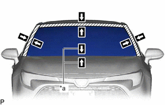
| *a | Matchmark |
Position the windshield glass sub-assembly.
Using suction cups, place the windshield glass sub-assembly in the correct position.
Check that the whole contact surface of the windshield glass sub-assembly rim is perfectly even.
Align the matchmarks on the windshield glass sub-assembly and vehicle body.
- NOTICE:
-
Check that the windshield glass stoppers are engaged to the vehicle body correctly.
Remove the windshield glass sub-assembly.
Using a brush, coat the installation surface on the vehicle body with body primer.
- NOTICE:
- ·
Do not coat the adhesive with body primer.
·Do not apply too much body primer.
·Allow the body primer to dry for 3 minutes or more.
·Throw away any leftover body primer.
- HINT:
-
If an area other than specified is coated by accident, wipe off the body primer with a clean piece of cloth before it dries.
Using a brush or sponge, coat the adhesive application area with glass primer.
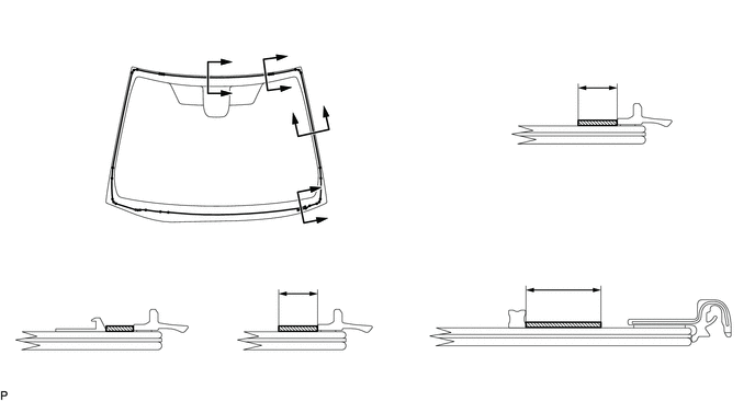
| *A | Back Side | - | - |
| *a | Adhesive Application Area | *b | Ceramic Notch |
|
|
Glass Primer | - | - |
- Standard Dimension:
Area Dimension a 8.1 mm (0.319 in.) or more b 8.1 mm (0.319 in.) or more c 19.0 mm (0.748 in.)
- NOTICE:
- ·
Do not apply too much glass primer.
·Allow the glass primer to dry for 3 minutes or more.
·Throw away any leftover glass primer.
- HINT:
- ·
Apply glass primer to the ceramic notches.
·If an area other than specified is coated by accident, wipe off the glass primer with a clean piece of cloth before it dries.
Apply adhesive to the windshield glass sub-assembly.
- Adhesive:
Toyota Genuine Windshield Glass Adhesive (High modulus type) or equivalent
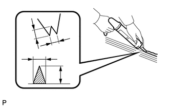
| *a | Nozzle |
Cut off the tip of the cartridge nozzle as shown in the illustration.
- Standard Dimension:
Area Dimension a 12.0 to 15.0 mm (0.472 to 0.591 in.) b 8.0 to 11.0 mm (0.315 to 0.433 in.)
Load the sealer gun with the cartridge.
Apply adhesive to the windshield glass sub-assembly as shown in the illustration.
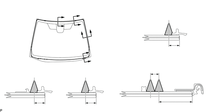
| *A | Back Side | - | - |
| *a | Adhesive Positioning Center | *b | Ceramic Notch |
|
|
Adhesive | - | - |
- Standard Dimension:
Area Dimension a 9.5 mm (0.374 in.) b 9.5 mm (0.374 in.) c 9.5 mm (0.374 in.) d 8.0 to 11.0 mm (0.315 to 0.433 in.) e 30.0 mm (1.181 in.)
- HINT:
-
Apply adhesive to the ceramic notches.
| *a | Matchmark |
Install the windshield glass sub-assembly.
Using suction cups, position the windshield glass sub-assembly so that the matchmarks are aligned, and press it in gently along the rim.
- NOTICE:
- ·
Check that the windshield glass stoppers are engaged to the vehicle body correctly.
·Check the clearance between the vehicle body and windshield glass sub-assembly.
Lightly press the outer surface of the windshield glass sub-assembly to ensure that the windshield glass sub-assembly is securely fit to the vehicle body.
- HINT:
-
Press the glass with a force of 98 N (10 kgf, 22.0 lbf) or more.
Using a scraper, remove any excess or protruding adhesive.
Hold the windshield glass sub-assembly using protective tape until the applied adhesive becomes hard.
- HINT:
-
Follow the instructions supplied by the adhesive manufacturer or in the corresponding instruction manual for the minimum amount of time necessary to wait before driving the vehicle.
When replacing the windshield glass sub-assembly or front window inner center moulding with a new one:
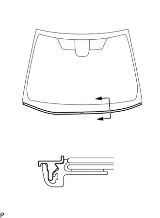
Remove the 2 protective retainers from the front window inner center moulding.
- NOTICE:
-
Do not damage the front window inner center moulding.
- HINT:
-
Make sure to remove the protective retainers.
7.INSPECT FOR LEAK
After the adhesive has hardened, apply water from the outside of the vehicle. Check that no water leaks into the cabin.
If water leaks into the cabin, allow the water to dry and add adhesive.
Remove the protective tape.
8.INSTALL ROOF HEADLINING ASSEMBLY
89941
9.INSTALL RAIN SENSOR (w/ Rain Sensor)
8646C
10.INSTALL FORWARD RECOGNITION CAMERA (w/ Pre-collision System)
for NR Series Engine: Click hereADAS / AD>ADVANCED DRIVER ASSISTANCE SYSTEM>FRONT CAMERA (for NR Series Engine)>INSTALLATION202304,999999,_95,_139716,_0584840,RM1000000029I34,
except NR Series Engine: Click hereADAS / AD>ADVANCED DRIVER ASSISTANCE SYSTEM>FRONT CAMERA (except NR Series Engine)>INSTALLATION202304,999999,_95,_139716,_0584196,RM1000000029F5K,
87810
11.INSTALL INNER REAR VIEW MIRROR ASSEMBLY
55708
12.INSTALL COWL TOP VENTILATOR LOUVER SUB-ASSEMBLY
55754F
13.INSTALL COWL WATER EXTRACT SHIELD LH
55753D
14.INSTALL COWL WATER EXTRACT SHIELD RH
- HINT:
-
Use the same procedure as for the LH side.
15.INSTALL FRONT WIPER ARM AND BLADE ASSEMBLY RH
16.INSTALL FRONT WIPER ARM AND BLADE ASSEMBLY LH
85292B
17.INSTALL FRONT WIPER ARM HEAD CAP