DOOR LOCK WIRELESS DOOR LOCK CONTROL SYSTEM(for NR Series Engine) Only Wireless Control Function is Inoperative
DESCRIPTION
When the wireless operation of the door lock function does not operate, a malfunction or wave interference may be occurring in either of the following: 1) the signal communication line between the electrical key and tire pressure monitoring system receiver assembly and certification ECU (smart key ECU assembly) (the line used for wireless operations): or 2) the electrical key transmitter sub-assembly. If the wireless lock operations cannot be performed, there may be electrical key transmitter sub-assembly malfunctions, wave interference or problems in the communication which is used for the wireless function between the electrical key and tire pressure monitoring system receiver assembly and certification ECU (smart key ECU assembly).
WIRING DIAGRAM
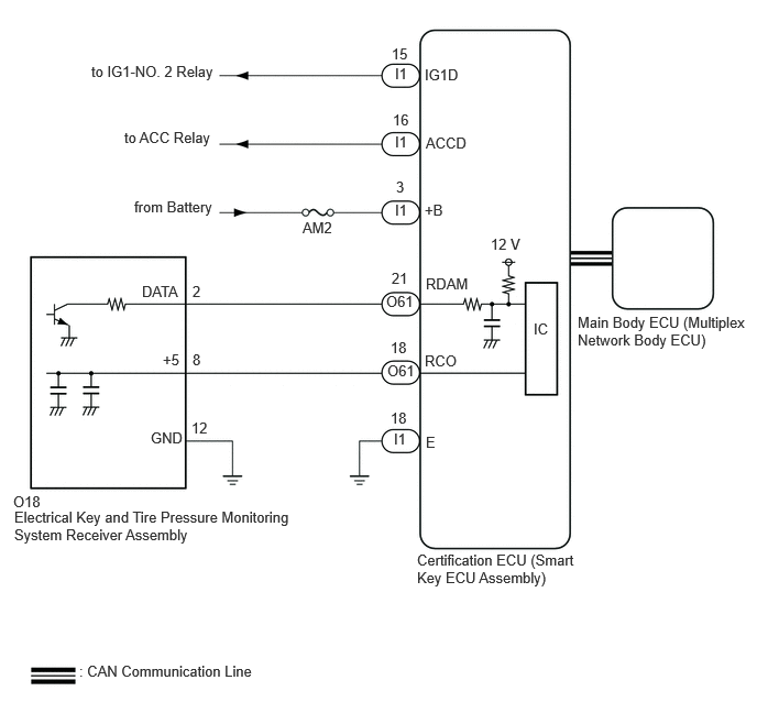
CAUTION / NOTICE / HINT
- NOTICE:
- ·
The wireless door lock control system uses the CAN communication system. Inspect the communication function by following How to Proceed with Troubleshooting. Troubleshoot the wireless door lock control system after confirming that the communication systems are functioning properly.
·Before replacing the main body ECU (multiplex network body ECU), refer to Service Bulletin.
·Before replacing the certification ECU (smart key ECU assembly) or electrical key transmitter sub-assembly, refer to Service Bulletin.
·Check that there are no electrical key transmitter sub-assemblies in the vehicle.
·Before performing the inspection, check that DTC B1242 (wireless door lock tuner circuit malfunction) is not output
·Inspect the fuses for circuits related to this system before performing the following procedure.
·After repair, confirm DTC does not reoccur by performing the "DTC Output Confirmation Operation".
·electrical key and tire pressure monitoring system receiver assembly has a constant voltage (5 V) supply circuit connected to terminal "+5".
·When replacing the electrical key and tire pressure monitoring system receiver assembly, read the transmitter IDs (tire pressure warning system) stored in the old ECU using the GTS and write them down before removal.
·If the electrical key and tire pressure monitoring system receiver assembly has been replaced, it is necessary to perform initialization (Click hereSuspension>TIRE PRESSURE MONITORING>TIRE PRESSURE WARNING SYSTEM (for Gasoline Model (for Type A))>INITIALIZATION202304,999999,_53,_080780,_0393955,RM100000002BB37,) after registration (Click hereSuspension>TIRE PRESSURE MONITORING>TIRE PRESSURE WARNING SYSTEM (for Gasoline Model (for Type A))>REGISTRATION202304,999999,_53,_080780,_0393955,RM100000002B0BZ,) of the transmitter IDs to the electrical key and tire pressure monitoring system receiver assembly.
PROCEDURE
Check the power door lock operation.
- OK:
Power door lock control function operates properly.
- Result:
Proceed to OK NG
OK
NG
Using another registered electrical key transmitter sub-assembly, check the wireless door lock control function.
- OK:
Wireless door lock control function operates properly.
- Result:
Proceed to OK NG
OK
NG
Check the transmitter battery level of the electrical key transmitter sub-assembly.
Press and hold the lock switch of the transmitter for 5 seconds and check the number of times that the transmitter LED illuminates.
- HINT:
-
The electrical key transmitter sub-assembly sends voltage information to the certification ECU (smart key ECU assembly) when it is being used. The certification ECU (smart key ECU assembly) displays "Yes" for the "Key Low Battery" item of the Data List when this voltage information indicates 2.2 V or less.
- Result:
Result Proceed to Transmitter LED does not illuminate when switch is pressed and held A Transmitter LED illuminates 3 times or more when switch is pressed and held B Transmitter LED illuminates once or twice but not a third time C
A
B
C
Inspect the transmitter battery capacity.
- Result:
Proceed to OK NG
OK
NG
Bring the electrical key and tire pressure monitoring system receiver assembly and perform a wireless operation check.
- HINT:
- ·
When the electrical key transmitter sub-assembly is brought near the electrical key and tire pressure monitoring system receiver assembly, the possibility of wave interference decreases, and it can be determined if wave interference is causing the problem symptom.
·If the inspection result is that the problem only occurs in certain locations or times of day, the possibility of wave interference is high. Also, added vehicle components may cause wave interference. If installed, remove them and perform the operation check.
- OK:
Wireless function operates properly.
- Result:
Proceed to OK NG
OK
NG
Connect the GTS to the DLC3.
Turn the engine switch on (IG).
Turn the GTS on.
Enter the following menus: Body Electrical / Power Source Control / Data List.
Read the Data List according to the display on the GTS.
Measure the voltage while checking the Data List on the GTS.
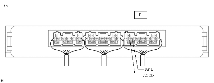
| *a | Component with harness connected
(Certification ECU (Smart Key ECU Assembly)) |
- | - |
- Body Electrical > Power Source Control > Data List
-
Tester Display Measurement Item Range Normal Condition Diagnostic Note Power Supply Condition Power supply state All OFF, ACC ON, IG ON or ST ON All OFF: Engine switch off (ACC and IG)
ACC ON: Engine switch on (ACC)
IG ON: Engine switch on (IG)
ST ON: Sending engine start request signal-
- Body Electrical > Power Source Control > Data List
-
Tester Display Power Supply Condition - 50003 223 18
- Standard Voltage:
Tester Connection Condition Specified Condition I1-15 (IG1D) - Body ground Engine switch off Below 1 V Engine switch on (ACC) Below 1 V Engine switch on (IG) 9 V or higher I1-16 (ACCD) - Body ground Engine switch off Below 1 V Engine switch on (ACC) 9 V or higher Engine switch on (IG) 9 V or higher
- Result:
Proceed to OK NG
OK
NG
Enter the following menus: Body Electrical / Main Body / Data List.
Read the Data List according to the display on the GTS.
- Body Electrical > Main Body > Data List
-
Tester Display Measurement Item Range Normal Condition Diagnostic Note ACC SW Engine switch on (ACC) signal OFF or ON OFF: Engine switch off
ON: Engine switch on (ACC)- IG SW Engine switch on (IG) signal OFF or ON OFF: Engine switch off or on (ACC)
ON: Engine switch on (IG)-
- Body Electrical > Main Body > Data List
-
Tester Display ACC SW IG SW - 50003 123 31,30
- Result:
Proceed to OK NG
OK
NG
Disconnect the O61 certification ECU (smart key ECU assembly) connector.
Disconnect the O18 electrical key and tire pressure monitoring system receiver assembly connector.
Measure the resistance according to the value(s) in the table below.
- Standard Resistance:
Tester Connection Condition Specified Condition O61-18 (RCO) - O18-8 (+5) Always Below 1 Ω O61-21 (RDAM) - O18-2 (DATA) Always Below 1 Ω O18-12 (GND) - Body ground Always Below 1 Ω O61-18 (RCO) or O18-8 (+5) - Other terminals and body ground Always 10 kΩ or higher O61-21 (RDAM) or O18-2 (DATA) - Other terminals and body ground Always 10 kΩ or higher
- Result:
Proceed to OK NG
OK
NG

| *A | except M20A-FKS, M20E-FKS |
| *B | for M20A-FKS, M20E-FKS |
| *a | Component with harness connected
(Electrical Key and Tire Pressure Monitoring System Receiver Assembly) |
Measure the resistance according to the value(s) in the table below.
Reconnect the I1 certification ECU (smart key ECU assembly) connector.
Check for pulses according to the value(s) in the table below.
- Standard Pulses:
Tester Connection Condition Specified Condition O18-2 (DATA) - O18-12 (GND) Procedure:
1.Turn engine switch off
2.Lock all doors
3.Bring electrical key transmitter sub-assembly wireless function operational area
4.Press lock or unlock switch of electrical key transmitter sub-assembly
Pulse generation
- Result:
Proceed to OK NG
OK
NG
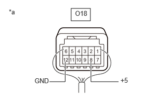
| *a | Component with harness connected
(Electrical Key and Tire Pressure Monitoring System Receiver Assembly) |
Check for pulses according to the value(s) in the table below.
- Standard Pulses:
Tester Connection Condition Specified Condition O18-8 (+5) - O18-12 (GND) Procedure:
1.Turn engine switch off
2.Bring electrical key transmitter sub-assembly wireless function operational area
3.Press lock or unlock switch of electrical key transmitter sub-assembly
Pulse generation
- Result:
Proceed to OK NG
OK
NG
Temporarily replace the certification ECU (smart key ECU assembly) with a new one.
- HINT:
-
Refer to the Service Bulletin.
- Result:
Proceed to NEXT
NEXT
Check the wireless door lock operation.
- OK:
Wireless door lock function operates properly.
- Result:
Proceed to OK NG
OK
NG