NAVIGATION / MULTI INFO DISPLAY NAVIGATION SYSTEM(for 10.25 Inch Display) Microphone Circuit
WIRING DIAGRAM
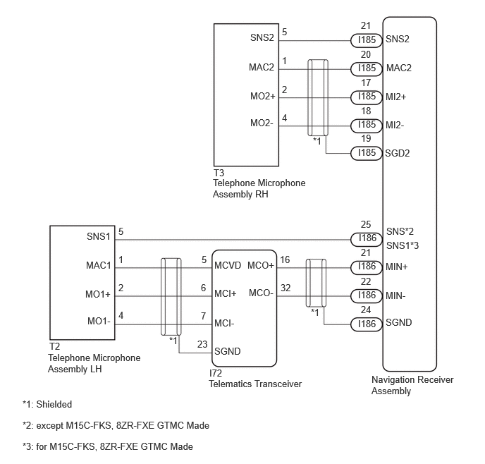
CAUTION / NOTICE / HINT
- NOTICE:
- ·
When replacing the telematics transceiver, make sure to replace it with a new one.
·Depending on the parts that are replaced during vehicle inspection or maintenance, performing initialization, registration or calibration may be needed.
·Before replacing the telematics transceiver, refer to Service Bulletin.
PROCEDURE
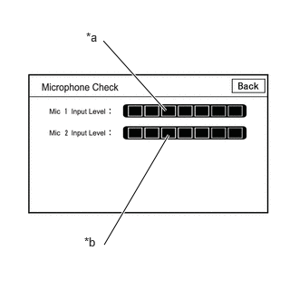
| *a | Microphone 1 input level gauge |
| *b | Microphone 2 input level gauge |
Enter diagnostic mode.
Select "Function Check/Setting" from the "Service Menu" screen.
Select "Microphone Check" from the "Function Check/Setting I" screen.
Speak into each microphone assembly and check the microphone input level gauge display.
- OK:
The microphone input levels of the gauge change in accordance with the voice.
- Result:
Result Proceed to Microphone input levels change for microphone 1 and 2 A Microphone input level does not change for microphone 1 B Microphone input level does not change for microphone 2 C
A
B
C
- HINT:
-
Measure the connector of the telematics transceiver while it is connected.
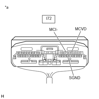
| *a | Component with harness connected
(Telematics Transceiver) |
Measure the resistance according to the value(s) in the table below.
- Standard Resistance:
Tester Connection Condition Specified Condition I72-7 (MCI-) - Body ground Always Below 1 Ω I72-23 (SGND) - Body ground Always Below 1 Ω
Measure the voltage according to the value(s) in the table below.
- Standard Voltage:
Tester Connection Condition Specified Condition I72-5 (MCVD) - Body ground Ignition switch ON 7.5 to 8.5 V
- Result:
Proceed to OK NG
OK
NG
- HINT:
-
Measure the connector of the telematics transceiver while it is connected.
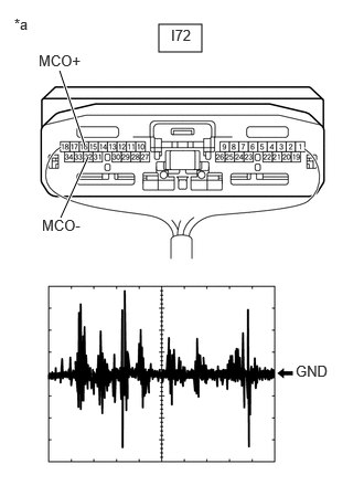
| *a | Component with harness connected
(Telematics Transceiver) |
Using an oscilloscope, measure the waveform according to the condition(s) in the table below.
| Item | Condition |
|---|---|
| Tester Connection | I72-16 (MCO+) - I72-32 (MCO-) |
| Tool setting | 50 mV/DIV., 500 ms/DIV. |
| Vehicle condition | 1.
Turn the ignition switch to ON 2.
Sound is input to the telephone microphone assembly when the user is closer than 125 mm from the telephone microphone assembly LH sound holes in the roof headlining holder cover |
- OK:
The waveform is similar to that shown in the illustration.
- HINT:
- ·
The oscilloscope waveform shown in the illustration is an example for reference only.
·In order to ensure that a consistent sound level is input to the microphone, use a digital voice recorder, etc., to play back sound in the same location with respect to the microphone.
- Result:
Result Proceed to A waveform synchronized with voice signals is output A A waveform synchronized with voice signals is not output B
A
B
Disconnect the I186 navigation receiver assembly connector.
Disconnect the I72 telematics transceiver connector.
Measure the resistance according to the value(s) in the table below.
- Standard Resistance:
Tester Connection Condition Specified Condition I186-21 (MIN+) - I72-16 (MCO+) Always Below 1 Ω I186-22 (MIN-) - I72-32 (MCO-) Always Below 1 Ω I186-21 (MIN+) or I72-16 (MCO+) - Body ground Always 10 kΩ or higher I186-22 (MIN-) or I72-32 (MCO-) - Body ground Always 10 kΩ or higher I186-24 (SGND) - Body ground Always 10 kΩ or higher
- Result:
Proceed to OK NG
OK
NG
Disconnect the I186 navigation receiver assembly connector.
Disconnect the I72 telematics transceiver connector.
Measure the resistance according to the value(s) in the table below.
- Standard Resistance:
Tester Connection Condition Specified Condition I186-21 (MIN+) - I72-16 (MCO+) Always Below 1 Ω I186-22 (MIN-) - I72-32 (MCO-) Always Below 1 Ω I186-21 (MIN+) or I72-16 (MCO+) - Body ground Always 10 kΩ or higher I186-22 (MIN-) or I72-32 (MCO-) - Body ground Always 10 kΩ or higher I186-24 (SGND) - Body ground Always 10 kΩ or higher
- Result:
Proceed to OK NG
OK
NG
Disconnect the I72 telematics transceiver connector.
Disconnect the T2 telephone microphone assembly LH connector.
Measure the resistance according to the value(s) in the table below.
- Standard Resistance:
Tester Connection Condition Specified Condition I72-5 (MCVD) - T2-1 (MAC1) Always Below 1 Ω I72-6 (MCI+) - T2-2 (MO1+) Always Below 1 Ω I72-7 (MCI-) - T2-4 (MO1-) Always Below 1 Ω I72-5 (MCVD) or T2-1 (MAC1) - Body ground Always 10 kΩ or higher I72-6 (MCI+) or T2-2 (MO1+) - Body ground Always 10 kΩ or higher I72-7 (MCI-) or T2-4 (MO1-) - Body ground Always 10 kΩ or higher I72-23 (SGND) - Body ground Always 10 kΩ or higher
- Result:
Proceed to OK NG
OK
NG
Disconnect the I186 navigation receiver assembly connector.
Disconnect the T2 telephone microphone assembly LH connector.
Measure the resistance according to the value(s) in the table below.
- Standard Resistance:
Tester Connection Condition Specified Condition *1: except M15C-FKS, 8ZR-FXE GTMC Made
*2: for M15C-FKS, 8ZR-FXE GTMC Made
I186-25 (SNS) - T2-5 (SNS1)*1 Always Below 1 Ω I186-25 (SNS1) - T2-5 (SNS1)*2 Always Below 1 Ω I186-25 (SNS) or T2-5 (SNS1) - Body ground Always 10 kΩ or higher I186-25 (SNS1) or T2-5 (SNS1) - Body ground*2 Always 10 kΩ or higher
- Result:
Proceed to OK NG
OK
NG
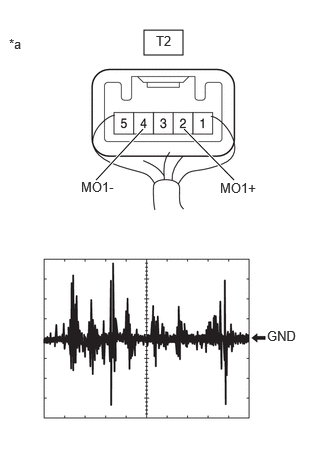
| *a | Component with harness connected
(Telephone Microphone Assembly LH) |
Using an oscilloscope, measure the waveform according to the condition(s) in the table below.
| Item | Condition |
|---|---|
| Tester Connection | T2-2 (MO1+) - T2-4 (MO1-) |
| Tool setting | 50 mV/DIV., 500 ms/DIV. |
| Vehicle condition | 1.
Turn the ignition switch to ON 2.
Sound is input to the telephone microphone assembly when the user is closer than 125 mm from the telephone microphone assembly LH sound holes in the roof headlining holder cover |
- OK:
The waveform is similar to that shown in the illustration.
- HINT:
- ·
The oscilloscope waveform shown in the illustration is an example for reference only.
·In order to ensure that a consistent sound level is input to the microphone, use a digital voice recorder, etc., to play back sound in the same location with respect to the microphone.
- Result:
Result Proceed to A waveform synchronized with voice signals is output A A waveform synchronized with voice signals is not output B
A
B
Disconnect the I72 telematics transceiver connector.
Disconnect the T2 telephone microphone assembly LH connector.
Measure the resistance according to the value(s) in the table below.
- Standard Resistance:
Tester Connection Condition Specified Condition I72-5 (MCVD) - T2-1 (MAC1) Always Below 1 Ω I72-6 (MCI+) - T2-2 (MO1+) Always Below 1 Ω I72-7 (MCI-) - T2-4 (MO1-) Always Below 1 Ω I72-5 (MCVD) or T2-1 (MAC1) - Body ground Always 10 kΩ or higher I72-6 (MCI+) or T2-2 (MO1+) - Body ground Always 10 kΩ or higher I72-7 (MCI-) or T2-4 (MO1-) - Body ground Always 10 kΩ or higher I72-23 (SGND) - Body ground Always 10 kΩ or higher
- Result:
Proceed to OK NG
OK
NG
Disconnect the I186 navigation receiver assembly connector.
Disconnect the I72 telematics transceiver connector.
Measure the resistance according to the value(s) in the table below.
- Standard Resistance:
Tester Connection Condition Specified Condition I186-21 (MIN+) - I72-16 (MCO+) Always Below 1 Ω I186-22 (MIN-) - I72-32 (MCO-) Always Below 1 Ω I186-21 (MIN+) or I72-16 (MCO+) - Body ground Always 10 kΩ or higher I186-22 (MIN-) or I72-32 (MCO-) - Body ground Always 10 kΩ or higher I186-24 (SGND) - Body ground Always 10 kΩ or higher
- Result:
Proceed to OK NG
OK
NG
Disconnect the I185 navigation receiver assembly connector.
Disconnect the T3 telephone microphone assembly RH connector.
Measure the resistance according to the value(s) in the table below.
- Standard Resistance:
Tester Connection Condition Specified Condition I185-17 (MI2+) - T3-2 (MO2+) Always Below 1 Ω I185-18 (MI2-) - T3-4 (MO2-) Always Below 1 Ω I185-20 (MAC2) - T3-1 (MAC2) Always Below 1 Ω I185-21 (SNS2) - T3-5 (SNS2) Always Below 1 Ω I185-17 (MI2+) or T3-2 (MO2+) - Body ground Always 10 kΩ or higher I185-18 (MI2-) or T3-4 (MO2-) - Body ground Always 10 kΩ or higher I185-20 (MAC2) or T3-1 (MAC2) - Body ground Always 10 kΩ or higher I185-19 (SGD2) - Body ground Always 10 kΩ or higher I185-21 (SNS2) or T3-5 (SNS2) - Body ground Always 10 kΩ or higher
- Result:
Proceed to OK NG
OK
NG
With the I185 navigation receiver assembly connector connected, disconnect the T3 telephone microphone assembly RH connector.
Measure the resistance according to the value(s) in the table below.
- Standard Resistance:
Tester Connection Condition Specified Condition T3-4 (MO2-) - Body ground Always Below 1 Ω
Measure the voltage according to the value(s) in the table below.
- Standard Voltage:
Tester Connection Condition Specified Condition T3-1 (MAC2) - Body ground Ignition switch ON 7.5 to 8.5 V
- Result:
Proceed to OK NG
OK
NG
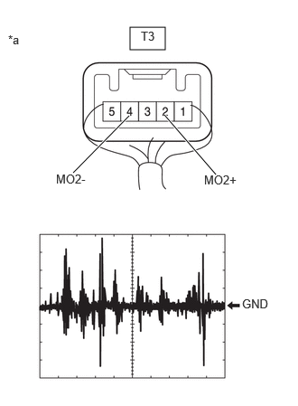
| *a | Component with harness connected
(Telephone Microphone Assembly RH) |
Using an oscilloscope, measure the waveform according to the condition(s) in the table below.
| Item | Condition |
|---|---|
| Tester Connection | T3-2 (MO2+) - T3-4 (MO2-) |
| Tool setting | 50 mV/DIV., 500 ms/DIV. |
| Vehicle condition | 1.
Turn the ignition switch to ON 2.
Sound is input to the telephone microphone assembly when the user is closer than 125 mm from the telephone microphone assembly RH sound holes in the roof headlining holder cover |
- OK:
The waveform is similar to that shown in the illustration.
- HINT:
- ·
The oscilloscope waveform shown in the illustration is an example for reference only.
·In order to ensure that a consistent sound level is input to the microphone, use a digital voice recorder, etc., to play back sound in the same location with respect to the microphone.
- Result:
Result Proceed to A waveform synchronized with voice signals is output A A waveform synchronized with voice signals is not output B
A
B