NAVIGATION / MULTI INFO DISPLAY NAVIGATION SYSTEM(for 10.25 Inch Display) DIAGNOSIS SYSTEM
CHECK FOR DTCs (USING SYSTEM CHECK MODE SCREEN)
- HINT:
- ·
When system self-diagnosis DTCs cannot be output due to a malfunction that is preventing diagnosis mode from being started or the multi-display from displaying, read the DTCs using the GTS.
·Depending on the multi-display settings, the background will remain started even when the ignition switch is turned off. For that reason, check the multi-display setting before performing an inspection.
Start diagnosis and display the "Service Menu" screen.
Select "Failure Diagnosis" on the service menu screen to display the failure diagnosis screen.
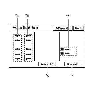
Select "System Check" of the failure diagnosis screen to display the system check mode screen.
| Display | Content |
|---|---|
| *a: Device Name List | Displays the components names, including additional devices (the physical address is displayed if the name is unknown) |
| *b: Check Result | Displays the inspection result of connected devices |
| *c: Optional Device Name List | Displays the components names, including aftermarket devices |
| *d: Memory Clear | Clears current DTCs and confirmed DTCs (press and hold for 3 seconds or more) |
| *e: Recheck | Performs a check again |
Confirm that each of the following connected devices are displayed:
| Name | Component | Connection Method |
|---|---|---|
| AVN | Navigation receiver assembly | - |
| DCM | Telematics transceiver | USB |
- HINT:
- ·
When diagnosis starts, the system check mode screen is displayed and the check is performed.
·System check mode displays the inspection results screen based on the response for each device during "system inspection instruction", "system inspection result demand", etc., and "Normal Diagnosis Notice" , notifications.
·The displayed screen is an example only. The actual device name displayed on the screen may differ depending on the connected device (dealer installed options, etc.).
CHECK SYSTEM CHECK RESULTS (USB/LOCAL BUS CONNECTED DEVICES)
| Check result | Meaning |
|---|---|
|
*: When the "DETAIL" button is pressed, the system transitions to the unit check mode screen. |
|
| OK | No DTCs are stored |
| DETAIL
(*) |
DTCs are stored |
| NCON | ·
A device that was previously registered to the system is not responding during registration ·
Cannot confirm a connection of a device that was previously registered to the system |
| NRES | No response of diagnosis information |
| Device name and/or system check result cannot be displayed for USB/LOCAL BUS CONNECTED DEVICES | No history of a device being registered to the system, and no response during the diagnosis check |
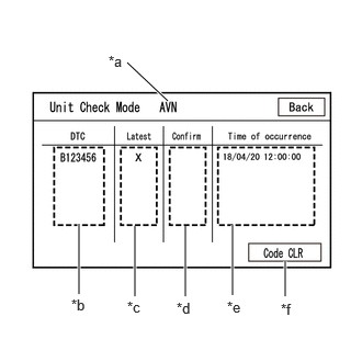
Unit Check Mode
When "DETAIL" is displayed on the system check mode inspection results, the system transitions to the unit check mode screen when pressed.
Confirm and record the DTCs
| Display | Content |
|---|---|
| *a: Device name | Target device name |
| *b: History DTC | Displays stored DTCs (up to 6 items) for the target device |
| *c: Latest | An "X" is displayed for the target device when latest DTCs (latest malfunction in current trip) exist |
| *d: Confirm | An "X" is displayed for the target device when confirmed DTCs (diagnosis trouble codes that have been confirmed up until the current time) exist |
| *e: Time of occurrence | Displays the time that the DTC was stored |
| *f: Code CLR | Clears DTC information of the target device and clears the display |
- NOTICE:
-
A maximum of 6 codes are stored for the navigation receiver assembly. When it is suspected that more than 6 codes are output, confirm the DTCs using the GTS.
- HINT:
-
Unit check mode screen is updated once per second.
CLEAR DTC (USING SYSTEM CHECK MODE SCREEN)
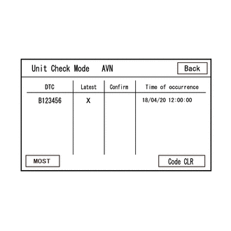
Clear the DTCs
Select "Code CLR" on the unit check mode screen (press and hold for 3 seconds or more) and clear the DTCs.
ENTER DIAGNOSTIC MODE
- HINT:
- ·
When system self-diagnosis DTCs cannot be output due to a malfunction that is preventing diagnosis mode from being started or the multi-display from displaying, read the DTCs using the GTS.
·Enter diagnostic mode by performing one of the following methods.
Start method 1
Using the GTS, display the diagnostic mode window.
- Body Electrical > Navigation System > Utility
-
Tester Display Diagnostic Mode - 50005 496 2765
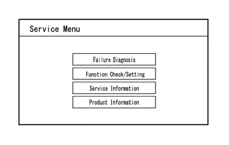
When diagnosis starts, the "Service Menu" screen is displayed.
Start method 2
Ensure that the vehicle is stopped.
Turn the ignition switch to ON.
Turn off the multi-display.
Turn off the audio of the navigation receiver assembly.

Flick the multi-display 5 times from left to right as shown in the illustration.
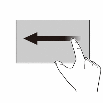
Flick the multi-display 5 times from right to left as shown in the illustration.
- HINT:
-
Make sure to complete the operation within 15 seconds of performing the initial flick from left to right.
When diagnosis starts, the service menu screen is displayed.
- HINT:
-
If diagnosis does not start due to a failed operation, turn the display on then off and perform the procedure from the start. (Only turning the audio of the navigation receiver assembly from off to on is not a valid method)
DIAGNOSTIC MODE SCREEN TRANSITION
Service Menu
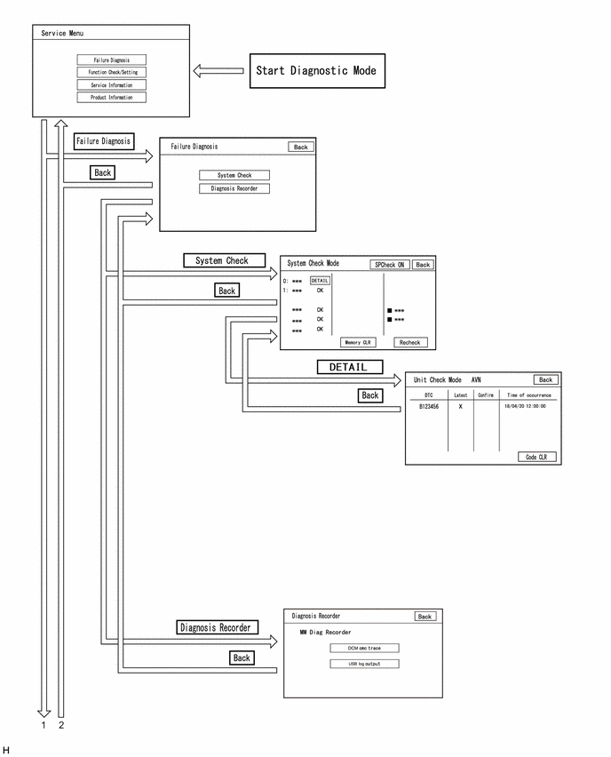
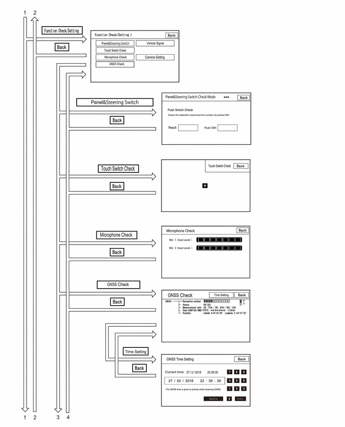
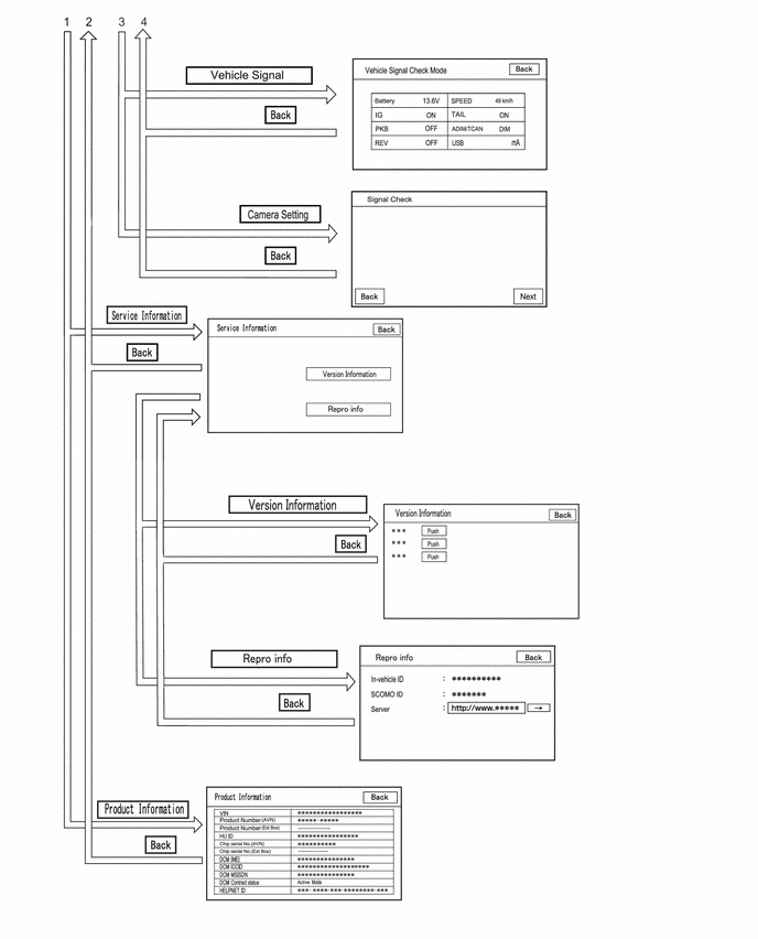
CANCEL DIAGNOSTIC MODE
- HINT:
-
There are 2 methods to cancel diagnosis
Cancellation method 1
Turn the ignition switch off.
Cancellation method 2
Turn off the navigation receiver assembly.
SERVICE MENU
- HINT:
-
The service menu screen can be used to perform malfunction diagnosis for each device, confirm functions and information, and collect data.
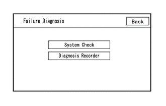
Failure Diagnosis
| Display | Details | Link |
|---|---|---|
| System Check | Display the names of devices connected to the system, and display current and confirmed DTCs as diagnosis results for those devices. | ( 202307,999999,_56,_080752,_0599611,RM100000002CWHS,) 202307,999999,_56,_080752,_0599611,RM100000002CWHS,)
|
| Diagnosis Recorder | "Bluetooth" connection history and Wi-Fi connection history can be confirmed | - |
- HINT:
-
Each failure diagnosis screen is created by the navigation receiver assembly.
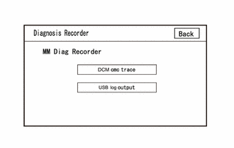
Diagnosis Recorder
| Display | Details | Link |
|---|---|---|
| DCM cmc trace | DCM cmc trace file can be saved | (202304,999999,_56,_080752,_0599611,RM100000002B8VJ,)
|
| USB log output | USB log file can be saved |
- HINT:
-
Each diagnosis recorder screen is created by the navigation receiver assembly.
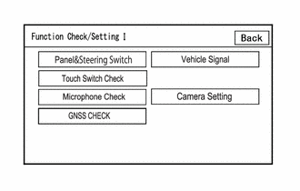
Function Check/Setting I
| Display | Content | Link |
|---|---|---|
| Panel&Steering Switch | Checks the operation of the panel switch and steering switch | (202304,999999,_56,_080752,_0599611,RM100000002B8VJ,)
|
| Touch Switch Check | Checks the operation of the touch switch of the multi-display | |
| Microphone Check | Checks the connection status of the microphone to the navigation receiver assembly | |
| System Sensors Check | ·
Displays GNSS related information ·
Sets GNSS date and time settings ·
Displays information regarding each sensor in the navigation receiver assembly |
|
| Vehicle Signal | Performs an inspection of vehicle side signal received by the navigation receiver assembly | |
| Camera Setting*1 | Performs adjustment of parking assist monitor system | (202304,999999,_56,_080754,_0596561,RM100000002AX0C,)
|
| Camera Setting*2 | Performs adjustment of panoramic view monitor system | (202307,999999,_56,_080754,_0612151,RM100000002CL9H,)
|
*1: w/ Parking Assist Monitor System
*2: w/ Panoramic View Monitor System
- HINT:
-
Each function check/setting I screen is created by the navigation receiver assembly.
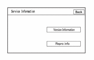
Service Information
- HINT:
-
The service information screen can be used to confirm information and read the memory.
| Display | Content | Link |
|---|---|---|
| Version Information | Displays connected device version information | - |
| Repro info | Displays in-vehicle device ID, SCOMO ID, etc. | - |
- HINT:
-
Each service information screen is created by the navigation receiver assembly.
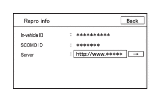
Repro info
| Display | Details |
|---|---|
| In-vehicle ID | Displays in-vehicle device ID of navigation receiver assembly |
| SCOMO ID | This item is displayed but is not used |
| Server | This item is displayed but is not used |
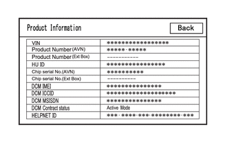
Product Information
| Display | Content |
|---|---|
| VIN | Displays VIN |
| Product Number (AVN) | Displays serial number of the navigation receiver assembly |
| Product Number (Ext Box) | This item is displayed but is not used |
| HU ID | Displays serial number of the navigation receiver assembly |
| Chip serial No. (AVN) | Displays IC serial number of the navigation receiver assembly |
| Chip serial No. (Ext Box) | This item is displayed but is not used |
| DCM IMEI | Displays telematics transceiver IMEI |
| DCM ICCID | Displays telematics transceiver ICCID |
| DCM MSISDN | Displays telematics transceiver MSISDN |
| DCM Contract status | Displays telematics transceiver contract status |
| HELPNET ID | Displays telematics transceiver HELPNET ID |