K313 CVT CONTINUOUSLY VARIABLE TRANSAXLE ASSEMBLY(When Using the Engine Support Bridge) REMOVAL
CAUTION / NOTICE / HINT
The necessary procedures (adjustment, calibration, initialization or registration) that must be performed after parts are removed and installed, or replaced during continuously variable transaxle assembly removal/installation are shown below.
| Replacement Part or Procedure | Necessary Procedure | Effect/Inoperative Function when Necessary Procedure not Performed | Link |
|---|---|---|---|
| Replacement of ECM | Perform Vehicle Identification Number (VIN) or frame number registration | DTC is stored | ( 201906,999999,_51,_080777,_0393969,RM100000001I1RD,) 201906,999999,_51,_080777,_0393969,RM100000001I1RD,)
|
1.
Reset memory 2.
Deceleration sensor zero point calibration 3.
CVT oil pressure calibration |
·
Large shift shock ·
Deterioration of fuel efficiency |
(201906,999999,_52,_080728,_0392261,RM100000001HP98,)
|
|
| Code registration (Immobiliser system) | Engine start | See Service Bulletin for the registration method | |
| Gas leaks from exhaust system | Inspection after repair | ·
Poor idle, etc. ·
Engine start function, etc. |
(201906,999999,_51,_080777,_0393969,RM100000001I1RE,)
|
| Replacement of starter assembly | Clear the number of starter operations | Stop and Start System | (201906,999999,_51,_080774,_0393362,RM100000001HXHH,)
|
| Replacement of battery | Integrated current value initialization | ||
| Replacement of continuously variable transaxle assembly | Air bleed the oil pump with motor assembly | Stop and Start System | (201906,999999,_51,_080774,_0393362,RM100000001HXHH,)
|
1.
Reset memory 2.
Deceleration sensor zero point calibration 3.
CVT oil pressure calibration |
·
Large shift shock ·
Deterioration of fuel efficiency |
(201906,999999,_52,_080728,_0392261,RM100000001HP98,)
|
|
| Replacement of CVT fluid | Air bleed the oil pump with motor assembly | Stop and Start System | (201906,999999,_51,_080774,_0393362,RM100000001HXHH,)
|
| ATF thermal degradation estimate reset | The value of the Data List item "ATF Thermal Degradation Estimate" is not estimated correctly | (201906,999999,_52,_080728,_0392261,RM100000001HP98,)
|
|
| Tires | Rear television camera assembly optical axis (Back camera position setting) | Parking Assist Monitor System | (202304,999999,_56,_080754,_0596561,RM100000002AX0C,)
|
| Suspension parts | Rear television camera assembly optical axis (Back camera position setting) | Parking Assist Monitor System | (202304,999999,_56,_080754,_0596561,RM100000002AX0C,)
|
| Front wheel alignment adjustment | 1.
Perform "Reset Memory" 2.
Perform acceleration sensor zero point calibration and store system information memorization |
·
VSC is disabled or malfunctions ·
DTCs are output ·
Slip indicator light illuminates ·
ABS warning light illuminates |
(202304,999999,_54,_080770,_0599814,RM100000002BA8F,)
|
- CAUTION:
- ·
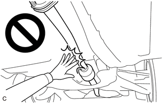
When the engine is hot, do not touch high-temperature areas such as the engine or exhaust pipe.
·Touching high-temperature areas such as the engine and exhaust pipe could result in burns.
·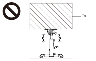 2.573,0.583 2.906,0.583 false 2.948,0.479 3.26,0.677 0.313,0.198 10 false *a
*a Heavy object exceeding the capacity of the transmission jack
Because the continuously variable transaxle assembly is extremely heavy, make sure to follow the work procedures described in the repair manual.
·If work is not performed according to the procedures described in the repair manual, there is a danger that the transmission jack could drop and components could fall down.
- HINT:
-
When the cable is disconnected / reconnected to the battery terminal, systems temporarily stop operating. However, each system has a function that completes learning the first time the system is used.
Learning completes when vehicle is driven Effect/Inoperative Function when Necessary Procedure not Performed Necessary Procedure Link Stop and Start System Idle the engine for approximately 5 to 60 minutes or drive the vehicle until stop and start control is permitted ( 201906,999999,_51,_080774,_0393362,RM100000001HXHC,)
Pre-collision System Perform steering sensor zero point calibration ( 202304,999999,_95,_139716,_0601175,RM100000002BFOE,)
Lane Tracing Assist System
PROCEDURE

 1. PRECAUTION
- NOTICE:
-
After turning the ignition switch off, waiting time may be required before disconnecting the cable from the negative (-) battery terminal.
2. ALIGN FRONT WHEELS FACING STRAIGHT AHEAD
3.DISCONNECT CABLE FROM NEGATIVE BATTERY TERMINAL
4.DRAIN ENGINE COOLANT
5.REMOVE FRONT DRIVE SHAFT ASSEMBLY (for TFTM Made)
6.REMOVE FRONT DRIVE SHAFT ASSEMBLY (for GTMC Made)
7.REMOVE WINDSHIELD WIPER MOTOR AND LINK ASSEMBLY
55737B
8.REMOVE NO. 1 HEATER AIR DUCT SPLASH SHIELD SEAL (w/ No. 1 Heater Air Duct Splash Shield Seal)
55701J
9.REMOVE OUTER COWL TOP PANEL SUB-ASSEMBLY
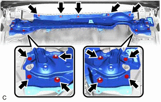
Remove the 9 bolts, 4 nuts and outer cowl top panel sub-assembly.
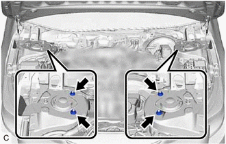
Install the 4 nuts.
- Torque:
- 50 N*m (510 kgf*cm, 37 ft.*lbf)
53289A
10.REMOVE RADIATOR SUPPORT OPENING COVER (for TFTM Made)
53289A
11.REMOVE RADIATOR SUPPORT OPENING COVER (for GTMC Made)
17751
12.REMOVE INLET NO. 1 AIR CLEANER
17705
13.REMOVE AIR CLEANER CAP WITH AIR CLEANER HOSE
17701
14.REMOVE AIR CLEANER CASE SUB-ASSEMBLY
89661
15.REMOVE ECM
16.REMOVE BATTERY
17.DISCONNECT ENGINE WIRE
74404A
18.REMOVE BATTERY CLAMP SUB-ASSEMBLY
33820B
19.DISCONNECT TRANSMISSION CONTROL CABLE ASSEMBLY
33823
20.REMOVE NO. 1 TRANSMISSION CONTROL CABLE BRACKET
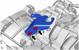
Remove the 2 bolts and No. 1 transmission control cable bracket from the continuously variable transaxle assembly.
35141F
21.DISCONNECT NO. 1 BREATHER PLUG (CVT)
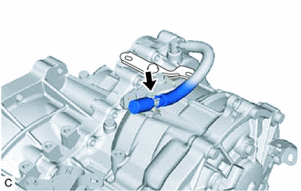
Disconnect the No. 1 breather plug (CVT) from the clamp.
58166A
22.REMOVE FRONT FLOOR COVER LH
58165C
23.REMOVE FRONT FLOOR COVER RH
57533B
24.REMOVE FRONT FLOOR CENTER BRACE
17410
25.REMOVE FRONT EXHAUST PIPE ASSEMBLY (TWC: Rear Catalyst)
82121
26.DISCONNECT ENGINE WIRE
Disconnect the transmission wire connector.
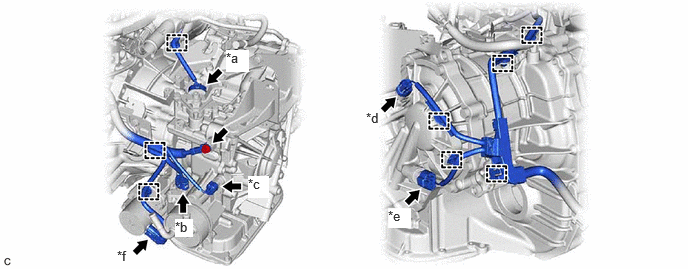
| *a | Park/Neutral Position Switch Assembly Connector | *b | Transmission Wire Connector |
| *c | Transmission Revolution Sensor (NIN) Connector | *d | Transmission Revolution Sensor (NOUT) Connector |
| *e | Oil Pressure Sensor Connector | *f | Oil Pump with Motor Assembly Connector |
Disconnect the transmission revolution sensor (NIN) connector.
Disconnect the park/neutral position switch assembly connector.
Disconnect the transmission revolution sensor (NOUT) connector.
Disconnect the oil pressure sensor connector.
Disconnect the oil pump with motor assembly connector.
Disengage the 8 clamps.
Remove the bolt to disconnect the engine wire from the continuously variable transaxle assembly.

Disengage the 3 clamps to disconnect the engine wire from the front suspension crossmember sub-assembly.
27.DISCONNECT WATER BY-PASS HOSE
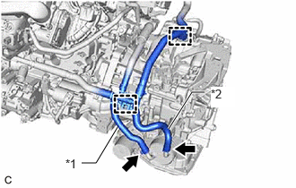
| *1 | No. 4 Water By-pass Hose |
| *2 | No. 3 Water By-pass Hose |
Slide the 2 clips and disconnect the No. 3 water by-pass hose and No. 4 water by-pass hose from the transmission oil cooler.
Disengage the 2 clamps to separate the water by-pass hose from the continuously variable transaxle assembly.
28100
28.REMOVE STARTER ASSEMBLY
29.REMOVE WIRE HARNESS CLAMP BRACKET
82286A
30.DISCONNECT NO. 2 EARTH WIRE
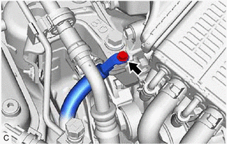
Remove the bolt to disconnect the No. 2 earth wire from the engine mounting insulator sub-assembly RH.
31.INSTALL ENGINE HANGERS
32.INSTALL ENGINE SUPPORT BRIDGE
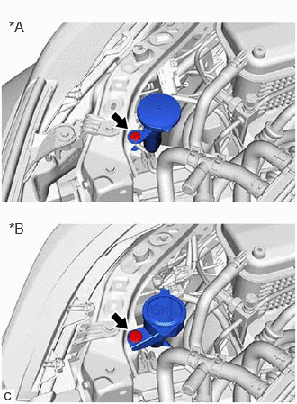
| *A | for TFTM Made |
| *B | for GTMC Made |
Remove the clip and disconnect the inlet hose from the vehicle body.
Install SST to the vehicle body as shown in the illustration.
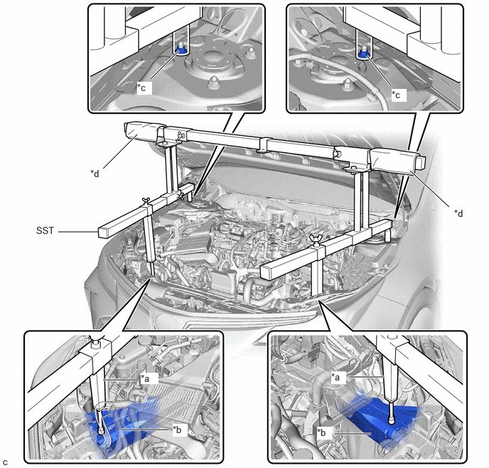
| *a | Support Shaft | *b | Front Side Member |
| *c | Nut | *d | Cloth |
- SST
- 09940-10010
- CAUTION:
- ·
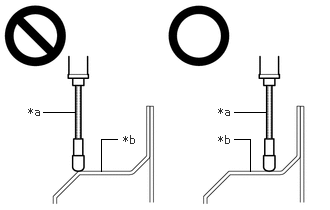 0.448,1.167 0.781,1.167 false 2.438,1.167 2.771,1.167 false 1.052,1.781 1.052,1.448 1.052,1.448 1.219,1.448 false 2.604,1.781 2.604,1.448 2.604,1.448 2.438,1.448 false 0.292,1.094 0.604,1.25 0.313,0.156 10 false *a 2.271,1.094 2.583,1.25 0.313,0.156 10 false *a 1.281,1.385 1.594,1.542 0.313,0.156 10 false *b 2.271,1.385 2.583,1.542 0.313,0.156 10 false *b
*a Support Shaft *b Front Side Member
Make sure that no oil or grease is on the front side member, and set the support shaft on the level surface of the front side member.
·The engine support bridge may fall off if any oil or grease is still on or it is installed on the unlevel surface.
- NOTICE:
- ·
Prevent SST from contacting the vehicle body exterior and windshield glass.
·To prevent damage to the engine hood, place pieces of cloth between the engine hood and SST.
·Lightly shake SST by hand to make sure it is securely installed before performing work.
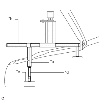
| *a | Support Shaft |
| *b | Sub Beam |
| *c | Front Side Member |
| *d | Threaded Portion |
Turn the threaded portion of each support shaft to adjust its height until the sub beams are parallel to the ground.
Install the chain block assembly to the sling bracket.
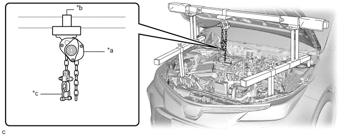
| *a | Chain Block Assembly | *b | Sling Bracket |
| *c | Fuse Shackle | - | - |
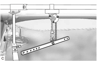
Install the division bar to the chain block assembly with the shackle (A).
- CAUTION:
- ·
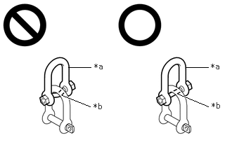
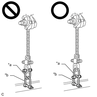 0.458,2.313 0.583,2.313 0.583,2.313 0.875,2.635 false 0.354,2.677 0.479,2.677 0.479,2.677 0.865,2.865 false 2.177,2.271 2.302,2.271 2.302,2.271 2.604,2.594 false 2.073,2.656 2.198,2.656 2.198,2.656 2.583,2.844 false 0.281,2.208 0.604,2.469 0.323,0.26 10 false *a 0.167,2.573 0.51,2.844 0.344,0.271 10 false *b 1.99,2.156 2.313,2.417 0.323,0.26 10 false *a 1.885,2.542 2.229,2.813 0.344,0.271 10 false *b
*a Fuse Shackle *b Shackle (A)
Make sure the fuse shackle is on the chain block assembly side and the shackle (A) is on the division bar side as shown in the illustration so that the fuse bolt is visible and can be checked for deformation easily.
·If the fuse shackle is installed upside down, deformation of the fuse bolt will not be visible and cannot be used to tell if the load capacity of the engine support bridge has been exceeded. If the load capacity is exceeded, it may cause the engine support bridge to damage the vehicle and the engine assembly with transaxle assembly may fall.
· 2.75,1 3.083,1 false 1.01,1 1.344,1 false 0.917,1.417 1.333,1.583 true 2.635,1.396 3.083,1.583 true 1.396,0.917 1.708,1.073 0.313,0.156 10 false *a 1.385,1.51 1.698,1.667 0.313,0.156 10 false *b 3.125,0.917 3.354,1.083 0.229,0.167 10 false *a 3.135,1.5 3.354,1.667 0.219,0.167 10 false *b
*a Fuse Shackle *b Fuse Bolt
Make sure that the fuse bolt of the fuse shackle is free of damage, such as deformation or cracks. If damaged, replace the fuse shackle.
·If a deformed fuse bolt is used, it cannot be used to tell if the load capacity of the engine support bridge has been exceeded. If the load capacity is exceeded, it may cause the engine support bridge to damage the vehicle and the engine assembly with transaxle assembly may fall.
Connect the division bar to the No. 1 engine hanger with the shackle (B).
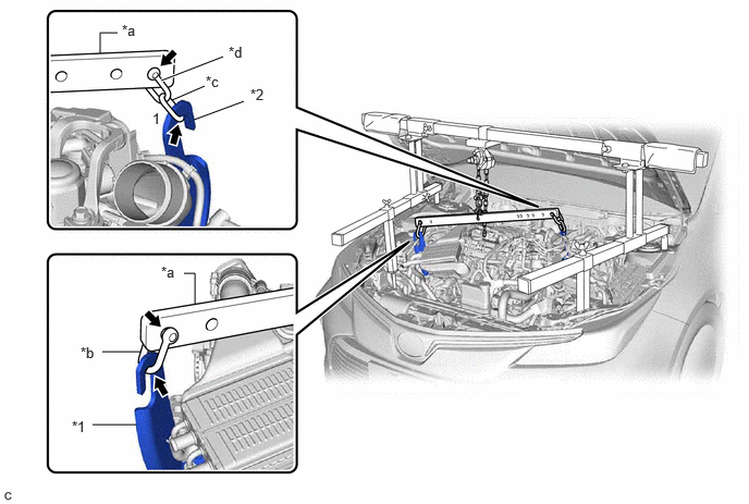
| *1 | No. 1 Engine Hanger | *2 | No. 2 Engine Hanger |
| *a | Division Bar | *b | Shackle (B) |
| *c | Chain | *d | Shackle (A) |
Connect the division bar to the No. 2 engine hanger with the shackle (A) and chain.
- NOTICE:
-
Connect the 1st link of the chain to the No. 2 engine hanger.
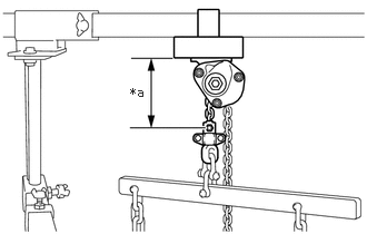
| *a | 120 mm (4.72 in.) or more |
Make sure the distance between the chain block assembly and suspension ring is 120 mm (4.72 in.) or more.
- HINT:
-
If the suspension height is less than 120 mm, adjust the links of the chain which connect the division bar and engine hanger.
Adjust the positions of the chain block assembly, support brackets and main beam so that the chain of the chain block assembly is perpendicular to the main beam and the length of the main beam on the outer side of the support bracket LH and RH is the same as shown in the illustration.
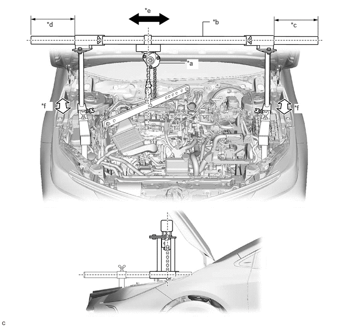
| *a | Chain Block Assembly | *b | Main Beam |
| *c | Dimension (A) | *d | Dimension (B) |
| *e | Right to Left Adjustment | *f | Front to Rear Adjustment |
- CAUTION:
- ·
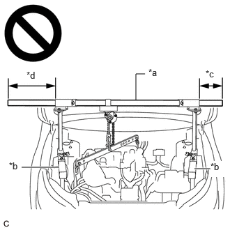 2.031,1.49 2.031,1.104 2.031,1.104 2.167,1.104 false 0.323,2.5 0.885,2.5 true 2.906,2.521 3.135,2.521 true 2.219,1 2.531,1.198 0.313,0.198 10 false *a 0.135,2.396 0.458,2.604 0.323,0.208 10 false *b 3.073,1.021 3.365,1.219 0.292,0.198 10 false *c 0.396,1.042 0.698,1.292 0.302,0.25 10 false *d 3.146,2.406 3.385,2.646 0.24,0.24 10 true *b
*a Main Beam *b Sub Beam *c Dimension (A) *d Dimension (B)
To prevent the engine assembly with transaxle assembly from falling, make sure that the length of dimension (A) and dimension (B) are equal.
·Do not perform any procedures if the length of dimension (A) and dimension (B) are not equal.
·Performing any procedure when the length of dimension (A) and dimension (B) are not equal may cause the engine assembly with transaxle assembly and engine support bridge to fall, possibly causing serious injury.
- NOTICE:
-
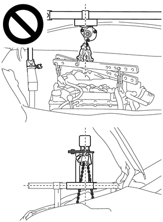
- ·
Do not perform any procedures if the chain of the chain block assembly is not straight.
·When removing the engine mount, if the chain of the chain block assembly is not straight, the engine assembly or transaxle assembly may contact the vehicle body.
Confirm the appropriate installation state of the engine support bridge and tighten the 6 wing bolts and 2 bolts.
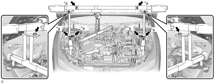
| *a | Wing Bolt | *b | Bolt |
- Torque:
- Bolt : 30 N*m (306 kgf*cm, 22 ft.*lbf)
- CAUTION:
- ·
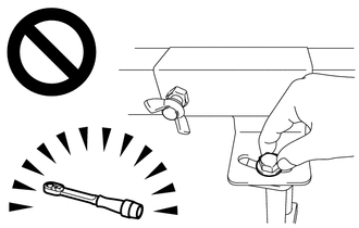
Do not perform any procedures before tightening the bolts to the specified torque.
·Performing procedures without tightening the bolts to the specified torque, may cause the engine support bridge to fall.
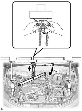
| *a | Turn |
Tighten the chain block assembly until it cannot be moved any further by hand.
- CAUTION:
-
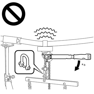 2.99,2.292 3.302,2.448 0.313,0.156 10 false *a
*a 41 N*m (418 kgf*cm, 30 ft.*lbf) or more
- ·
When suspending the engine assembly with transaxle assembly, do not tighten the chain block assembly more than 41 N*m (418 kgf*cm, 30 ft.*lbf).
·Tightening the chain block assembly more than 41 N*m (418 kgf*cm, 30 ft.*lbf) will cause the load capacity (400 kg (881.8 lb)) to be exceeded and may cause damage to the engine support bridge and vehicle body.
33.SECURE STEERING WHEEL
45259A
34.REMOVE COLUMN HOLE COVER SILENCER SHEET
45260
35.SEPARATE NO. 2 STEERING INTERMEDIATE SHAFT ASSEMBLY
45025D
36.SEPARATE NO. 1 STEERING COLUMN HOLE COVER SUB-ASSEMBLY
11361J
37.REMOVE FLYWHEEL HOUSING UNDER COVER
32101G
38.REMOVE DRIVE PLATE AND TORQUE CONVERTER ASSEMBLY SETTING BOLT
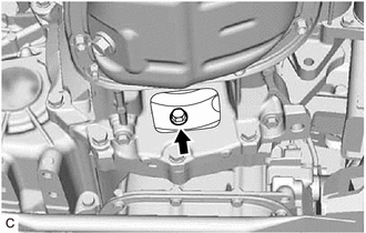
Turn the crankshaft to gain access to the 6 drive plate and torque converter assembly setting bolts and remove each drive plate and torque converter assembly setting bolt while holding the crankshaft pulley bolt with a wrench.
- HINT:
-
There will be one black colored drive plate and torque converter assembly setting bolt.
51108A
39.REMOVE REAR SIDE RAIL REINFORCEMENT SUB-ASSEMBLY LH
51107A
40.REMOVE REAR SIDE RAIL REINFORCEMENT SUB-ASSEMBLY RH
51201
41.REMOVE FRONT SUSPENSION CROSSMEMBER SUB-ASSEMBLY

Remove the bolt and separate the No. 2 engine moving control rod.
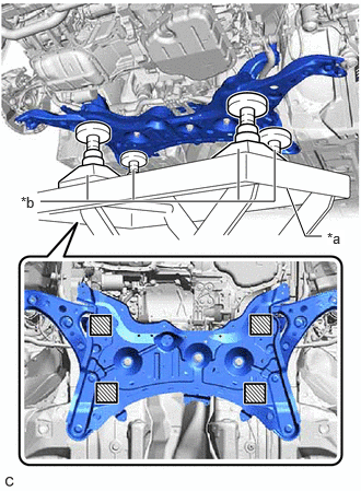
| *a | Engine Lifter |
| *b | Attachment |

|
Attachment placement location |
Support the front suspension crossmember sub-assembly with an engine lifter using 4 attachments or equivalent tools as shown in the illustration.
- CAUTION:
-
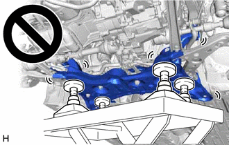
- ·
The front suspension crossmember sub-assembly is a very heavy component. Make sure that it is supported securely.
·If the front suspension crossmember sub-assembly is not securely supported, it may drop, resulting in serious injury.
- NOTICE:
-
Use attachments to keep the front suspension crossmember sub-assembly level.
Remove the 4 bolts and front suspension crossmember sub-assembly.
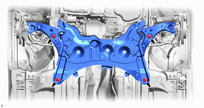
Slowly lower the front suspension crossmember sub-assembly.
- NOTICE:
-
When lowering the front suspension crossmember sub-assembly, be careful not to damage the vehicle body or other components installed to the vehicle.
12364B
42.REMOVE NO. 2 ENGINE MOVING CONTROL ROD
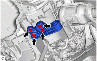
Remove the 4 bolts and No. 2 engine moving control rod from the continuously variable transaxle assembly.
30400
43.SUPPORT CONTINUOUSLY VARIABLE TRANSAXLE ASSEMBLY
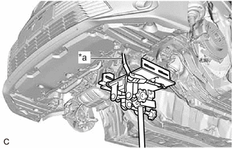
| *a | Lashing Belt |
Using a transmission jack, support the continuously variable transaxle assembly.
- NOTICE:
- ·
Adjust the attachment of the transmission jack to securely fix the continuously variable transaxle assembly to the transmission jack.
·To prevent the transaxle oil (CVT) pan sub-assembly from deforming, do not place any attachments under the transaxle oil (CVT) pan sub-assembly of the continuously variable transaxle assembly.
·Using a lashing belt or a rope, fix the continuously variable transaxle assembly to the transmission jack.
12372A
44.REMOVE ENGINE MOUNTING INSULATOR LH
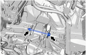
Remove the bolt and nut and separate the engine mounting insulator LH from the engine mounting bracket LH.
- NOTICE:
-
While holding the nut in place, loosen the bolt.
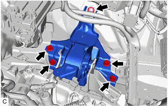
Remove the 4 bolts, nut and engine mounting insulator LH from the vehicle body.
30400
45.REMOVE CONTINUOUSLY VARIABLE TRANSAXLE ASSEMBLY
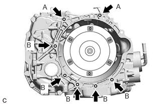
Remove the 7 bolts and continuously variable transaxle assembly from the engine assembly.
- NOTICE:
-
To prevent damage to the 2 knock pins, do not pry between the continuously variable transaxle assembly and engine assembly.
- HINT:
- ·
Bolt (A): Remove from the continuously variable transaxle assembly side.
·Bolt (B): Remove from the engine assembly side.
32000A
46.REMOVE TORQUE CONVERTER ASSEMBLY
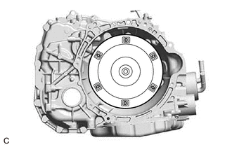
Remove the torque converter assembly from the continuously variable transaxle assembly.
- NOTICE:
-
Remove the torque converter assembly from the input shaft horizontally.
12318
47.REMOVE ENGINE MOUNTING STAY LH
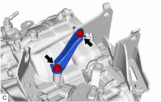
Remove the 2 bolts and engine mounting stay LH from the continuously variable transaxle assembly and engine mounting bracket LH.
12325A
48.REMOVE ENGINE MOUNTING BRACKET LH
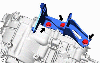
Remove the 3 bolts and engine mounting bracket LH from the continuously variable transaxle assembly.
87101A
49.REMOVE NO. 1 HEATER BRACKET SUB-ASSEMBLY
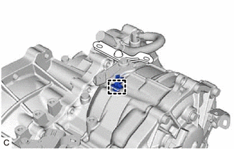
Remove the clamp from the No. 1 heater bracket sub-assembly.
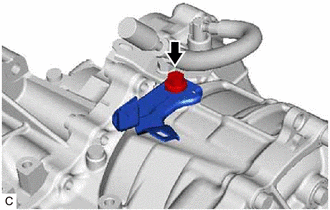
Remove the bolt and No. 1 heater bracket sub-assembly from the continuously variable transaxle assembly.
50.REMOVE WIRE HARNESS CLAMP BRACKET
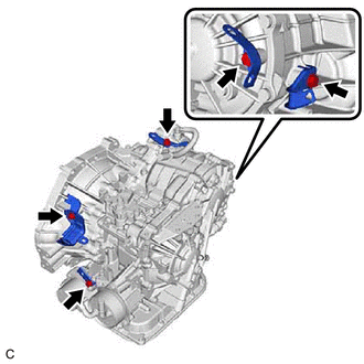
Remove the 5 bolts and 5 wire harness clamp brackets from the continuously variable transaxle assembly.
51.REMOVE STRAIGHT SCREW PLUG
- HINT:
-
Perform this procedure only when replacement of the straight screw plug is necessary.
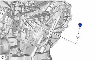
Remove the straight screw plug and gasket from the continuously variable transaxle assembly.
30400E
52.REMOVE CVT OIL PUMP TYPE T OIL SEAL
- NOTICE:
- ·
Do not remove the front oil pump assembly from the CVT main body, as there is a possibility of the entry of dust and foreign matter.
·Clean the work area, the tools to be used, and other equipment, etc. thoroughly before the operation, as there is the possibility that a CVT malfunction, which could prevent the vehicle from being able to be driven, could occur if dust or fine foreign matter enters the CVT.
·Do not use cotton work gloves, cloths, or paper towels, etc. that may produce lint, dust or foreign matter.
·Perform the operation as quickly as possible, as dust and foreign matter could enter the CVT while the torque converter assembly is removed.
·Do not use an air gun until the torque converter assembly has been installed, as it could cause dust and foreign matter to be stirred up.
Clean the tips of both the claws of SST and the center bolt.
- SST
- 09308-10010
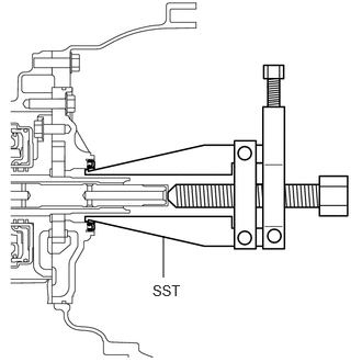
Using SST, remove the CVT oil pump type T oil seal.
- NOTICE:
-
Pay attention to the angle of the claws when opening them, and ensure that they do not come into contact with the oil pump housing, as there is the possibility that metal particles could be produced if they do.
32000A
53.INSPECT TORQUE CONVERTER ASSEMBLY
32101B
54.INSPECT DRIVE PLATE AND RING GEAR SUB-ASSEMBLY