DRIVE SHAFT / PROPELLER SHAFT FRONT DRIVE SHAFT ASSEMBLY(for TFTM Made) REMOVAL
CAUTION / NOTICE / HINT
The necessary procedures (adjustment, calibration, initialization, or registration) that must be performed after parts are removed and installed, or replaced during front drive shaft assembly removal/installation are shown below.
| Replaced Part or Performed Procedure | Necessary Procedure | Effect/Inoperative Function when Necessary Procedure not Performed | Link |
|---|---|---|---|
|
*: The vehicle height changes because of suspension or tire replacement. |
|||
| Front wheel alignment adjustment | for NR Series
·
Perform "Reset Memory" ·
Perform acceleration sensor zero point calibration and store system information memorization |
·
VSC is disabled or malfunctions ·
DTCs are output ·
Slip indicator light illuminates ·
ABS warning light illuminates |
( 202304,999999,_54,_080770,_0599814,RM100000002BA8F,) 202304,999999,_54,_080770,_0599814,RM100000002BA8F,)
|
except NR Series
·
Perform "Reset Memory" ·
Perform "Calibration" |
·
VSC is disabled or malfunctions ·
DTCs are output ·
Slip indicator light illuminates ·
ABS warning light illuminates |
(202304,999999,_54,_080770,_0599811,RM100000002B9XU,)
|
|
| Tires | Rear television camera assembly optical axis (Back camera position setting)* | Parking Assist Monitor System | (202304,999999,_56,_080754,_0596561,RM100000002AX0C,)
|
| CVT fluid | Air bleed the oil pump with motor assembly | Stop and Start System | (201906,999999,_51,_080774,_0393362,RM100000001HXHH,)
|
| ATF thermal degradation estimate reset | The value of the Data List item "ATF Thermal Degradation Estimate" is not estimated correctly | (201906,999999,_52,_080728,_0392261,RM100000001HP98,)for K313
( 202304,999999,_52,_101162,_0586431,RM100000002BEA5,)for K121
( 202304,999999,_52,_096216,_0597700,RM100000002B14E,)for K321
|
|
| Replaced Part or Performed Procedure | Necessary Procedure | Effect/Inoperative Function when Necessary Procedure not Performed | Link |
|---|---|---|---|
|
*: The vehicle height changes because of suspension or tire replacement. |
|||
| Front wheel alignment adjustment | 1.
Perform "Reset Memory" 2.
Perform "Calibration" |
·
DTCs are stored ·
ABS warning light illuminates ·
Brake system warning light (yellow indicator) illuminates ·
Slip indicator light illuminates ·
Electronically controlled brake system disabled or malfunctions |
(202304,999999,_54,_080770,_0392591,RM100000002B671,)
|
| Tires | Rear television camera assembly optical axis (Back camera position setting)* | Parking Assist Monitor System | (202304,999999,_56,_080754,_0596561,RM100000002AX0C,)
|
| Parking assist ECU initialization | Panoramic View Monitor System | (202307,999999,_56,_080754,_0612151,RM100000002CL9H,)
|
|
- HINT:
- ·
Use the same procedure for the RH side and LH side.
·The following procedure is for the LH side.
PROCEDURE

 1.REMOVE FRONT WHEELS
51410
2.REMOVE NO. 1 ENGINE UNDER COVER ASSEMBLY
for 8ZR-FXE: Click hereEngine / Hybrid System>8ZR-FXE (ENGINE MECHANICAL)>ENGINE ASSEMBLY>REMOVAL202307,999999,_51,_080726,_0391619,RM100000002CWTY_01_0301,
for NR Series Engine: Click hereEngine / Hybrid System>NR Series (ENGINE MECHANICAL)>ENGINE ASSEMBLY>REMOVAL202304,999999,_51,_080739,_0391935,RM100000002BCMQ_01_0388,
for M15B-FKS: Click hereEngine / Hybrid System>M15B-FKS (ENGINE MECHANICAL)>ENGINE ASSEMBLY>REMOVAL202304,999999,_51,_096197,_0454892,RM100000002BBF0_01_0306,
for M20A-FKS: Click hereEngine / Hybrid System>M20A-FKS (ENGINE MECHANICAL)>ENGINE ASSEMBLY>REMOVAL202304,999999,_51,_101145,_0470307,RM100000002BCP5_01_0306,
for M20E-FKS: Click hereEngine / Hybrid System>M20E-FKS (ENGINE MECHANICAL)>ENGINE ASSEMBLY>REMOVAL202304,999999,_51,_101154,_0476817,RM100000002BCQ9_01_0306,
for M20G-FXS: Click hereEngine / Hybrid System>M20F-FXS, M20G-FXS (ENGINE MECHANICAL)>ENGINE ASSEMBLY>REMOVAL202307,999999,_51,_146897,_0611496,RM100000002CJ20_01_0306,
51444A
3.REMOVE REAR ENGINE UNDER COVER LH
for 8ZR-FXE: Click hereEngine / Hybrid System>8ZR-FXE (ENGINE MECHANICAL)>ENGINE ASSEMBLY>REMOVAL202307,999999,_51,_080726,_0391619,RM100000002CWTY_01_0215,
for NR Series Engine: Click hereEngine / Hybrid System>NR Series (ENGINE MECHANICAL)>ENGINE ASSEMBLY>REMOVAL202304,999999,_51,_080739,_0391935,RM100000002BCMQ_01_0354,
for M15B-FKS: Click hereEngine / Hybrid System>M15B-FKS (ENGINE MECHANICAL)>ENGINE ASSEMBLY>REMOVAL202304,999999,_51,_096197,_0454892,RM100000002BBF0_01_0327,
for M20A-FKS: Click hereEngine / Hybrid System>M20A-FKS (ENGINE MECHANICAL)>ENGINE ASSEMBLY>REMOVAL202304,999999,_51,_101145,_0470307,RM100000002BCP5_01_0327,
for M20E-FKS: Click hereEngine / Hybrid System>M20E-FKS (ENGINE MECHANICAL)>ENGINE ASSEMBLY>REMOVAL202304,999999,_51,_101154,_0476817,RM100000002BCQ9_01_0327,
for M20G-FXS: Click hereEngine / Hybrid System>M20F-FXS, M20G-FXS (ENGINE MECHANICAL)>ENGINE ASSEMBLY>REMOVAL202307,999999,_51,_146897,_0611496,RM100000002CJ20_01_0327,
51443C
4.REMOVE REAR ENGINE UNDER COVER RH
for 8ZR-FXE: Click hereEngine / Hybrid System>8ZR-FXE (ENGINE MECHANICAL)>ENGINE ASSEMBLY>REMOVAL202307,999999,_51,_080726,_0391619,RM100000002CWTY_01_0251,
for NR Series Engine: Click hereEngine / Hybrid System>NR Series (ENGINE MECHANICAL)>ENGINE ASSEMBLY>REMOVAL202304,999999,_51,_080739,_0391935,RM100000002BCMQ_01_0361,
for M15B-FKS: Click hereEngine / Hybrid System>M15B-FKS (ENGINE MECHANICAL)>ENGINE ASSEMBLY>REMOVAL202304,999999,_51,_096197,_0454892,RM100000002BBF0_01_0328,
for M20A-FKS: Click hereEngine / Hybrid System>M20A-FKS (ENGINE MECHANICAL)>ENGINE ASSEMBLY>REMOVAL202304,999999,_51,_101145,_0470307,RM100000002BCP5_01_0328,
for M20E-FKS: Click hereEngine / Hybrid System>M20E-FKS (ENGINE MECHANICAL)>ENGINE ASSEMBLY>REMOVAL202304,999999,_51,_101154,_0476817,RM100000002BCQ9_01_0328,
for M20G-FXS: Click hereEngine / Hybrid System>M20F-FXS, M20G-FXS (ENGINE MECHANICAL)>ENGINE ASSEMBLY>REMOVAL202307,999999,_51,_146897,_0611496,RM100000002CJ20_01_0328,
5.DRAIN HYBRID TRANSAXLE FLUID (for Hybrid Transaxle)
6.DRAIN CONTINUOUSLY VARIABLE TRANSAXLE FLUID (for CVT)
for NR Series Engine: Click hereDrivetrain>K313 (CVT)>OIL PAN>REMOVAL201906,999999,_52,_080728,_0392268,RM100000001HPAR_02_0002,
for M15B-FKS: Click hereDrivetrain>K320 / K321 (CVT)>OIL PAN>REMOVAL202304,999999,_52,_096216,_0452222,RM1000000029R0L_02_0020,
for M20A-FKS: Click hereDrivetrain>K120 / K121 (CVT)>OIL PAN>REMOVAL202304,999999,_52,_101162,_0469759,RM1000000029GUI_02_0002,
for M20E-FKS: Click hereDrivetrain>K120 / K121 (CVT)>OIL PAN>REMOVAL202304,999999,_52,_101162,_0469759,RM1000000029GUI_02_0002,
43502H
7.REMOVE FRONT AXLE SHAFT NUT
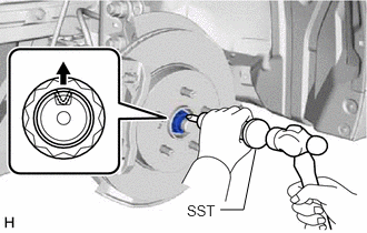
Using SST and a hammer, release the staked part of the front axle shaft nut.
- SST
- 09930-00010
- NOTICE:
-
Loosen the staked part of the front axle shaft nut completely, otherwise the threads of the drive shaft may be damaged.
While applying the brakes, remove the front axle shaft nut.
89543
8.SEPARATE FRONT SPEED SENSOR
45047
9.SEPARATE TIE ROD END SUB-ASSEMBLY
48810
10.SEPARATE FRONT STABILIZER LINK ASSEMBLY
48069
11.SEPARATE FRONT LOWER NO. 1 SUSPENSION ARM SUB-ASSEMBLY
12.SEPARATE FRONT DRIVE SHAFT ASSEMBLY
43420
13.REMOVE FRONT DRIVE SHAFT ASSEMBLY
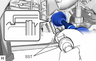
Using SST, remove the front drive shaft assembly.
- SST
- 09520-20010 (09521-02010, 09521-02040, 09521-02060)
09520-01011
- NOTICE:
- ·
Do not damage the front drive shaft oil seal.
·Do not damage the front axle inboard joint boot.
·Do not drop the front drive shaft assembly.
43420G
14.REMOVE FRONT DRIVE SHAFT HOLE SNAP RING
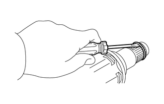
Using a screwdriver, remove the front drive shaft hole snap ring.