TIRE PRESSURE MONITORING TIRE PRESSURE WARNING SYSTEM(for Gasoline Model (for Type A)) C2198 Initialization Switch Error (for Test Diagnosis)
DESCRIPTION
The switch circuit inside the combination meter assembly turns on and off according to the steering pad switch assembly operation.
During test mode, the tire pressure warning light blinks at 0.125 second intervals when "Set Pressure" is selected on the multi-information display, and illuminates when the "OK" switch (steering pad switch assembly) is pressed.
| DTC No. | Detection Item | DTC Detection Condition | Trouble Area | Note |
|---|---|---|---|---|
| C2198 | Initialization Switch Error (for Test Diagnosis) | Test mode procedure is performed. | ·
Steering pad switch assembly ·
Spiral cable sub-assembly ·
Wire harness or connector ·
Tire pressure warning ECU and receiver |
- |
WIRING DIAGRAM
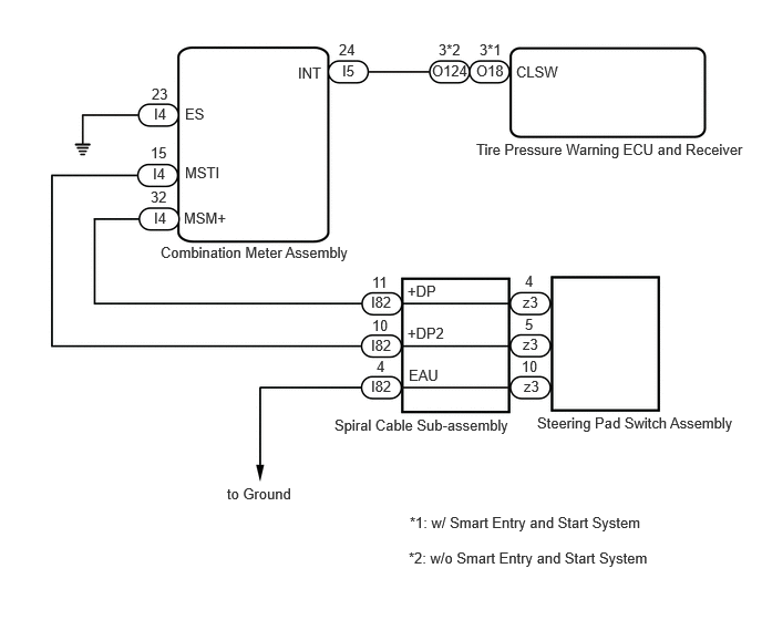
CAUTION / NOTICE / HINT
- NOTICE:
- ·
When replacing the tire pressure warning ECU and receiver, read the transmitter IDs and number of the transmitters (4 or 5) stored in the old ECU using the GTS and write them down before removal.
·It is necessary to perform initializationSuspension>TIRE PRESSURE MONITORING>TIRE PRESSURE WARNING SYSTEM (for Gasoline Model (for Type A))>INITIALIZATION202304,999999,_53,_080780,_0393955,RM100000002BB37, after registrationSuspension>TIRE PRESSURE MONITORING>TIRE PRESSURE WARNING SYSTEM (for Gasoline Model (for Type A))>REGISTRATION202304,999999,_53,_080780,_0393955,RM100000002B0BZ, of the transmitter IDs into the tire pressure warning ECU and receiver if the ECU has been replaced.
PROCEDURE
Remove the steering pad switch assembly.
Inspect the steering pad switch assembly.
- Result:
Proceed to OK NG
OK
NG
Remove the spiral cable sub-assembly.
Inspect the spiral cable sub-assembly.
- Result:
Proceed to OK NG
OK
NG
Disconnect the I82 spiral cable sub-assembly connector.
Disconnect the I4 combination meter assembly connector.
Measure the resistance according to the value(s) in the table below.
- Standard Resistance:
Tester Connection Condition Specified Condition I82-11 (+DP) - I4-32 (MSM+) Always Below 1 Ω I82-11 (+DP) or I4-32 (MSM+) - Body ground Always 10 kΩ or higher I82-10 (+DP2) - I4-15 (MSTI) Always Below 1 Ω I82-10 (+DP2) or I4-15 (MSTI) - Body ground Always 10 kΩ or higher
- Result:
Proceed to OK NG
OK
NG
Disconnect the O18*1 or O124*2 tire pressure warning ECU and receiver connector.
*1: w/ Smart Entry and Start System
*2: w/o Smart Entry and Start System
Disconnect the I4 and I5 combination meter assembly connectors.
Measure the resistance according to the value(s) in the table below.
- Standard Resistance:
w/ Smart Entry and Start System Tester Connection Condition Specified Condition O18-3 (CLSW) - I5-24 (INT) Always Below 1 Ω O18-3 (CLSW) or I5-24 (INT) - Body ground Always 10 kΩ or higher I4-23 (ES) - Body ground Always Below 1 Ω
w/o Smart Entry and Start System Tester Connection Condition Specified Condition O124-3 (CLSW) - I5-24 (INT) Always Below 1 Ω O124-3 (CLSW) or I5-24 (INT) - Body ground Always 10 kΩ or higher I4-23 (ES) - Body ground Always Below 1 Ω
- Result:
Proceed to OK NG
OK
NG
Disconnect the O18*1 or O124*2 tire pressure warning ECU and receiver connector.
*1: w/ Smart Entry and Start System
*2: w/o Smart Entry and Start System
Disconnect the I5 combination meter assembly connector.
Measure the voltage according to the value(s) in the table below.
- Standard Voltage:
Tester Connection Condition Specified Condition I5-24 (INT) - Body ground Ignition switch ON 8 to 15 V
- Result:
Proceed to OK NG
OK
NG