BRAKE CONTROL / DYNAMIC CONTROL SYSTEMS ELECTRONICALLY CONTROLLED BRAKE SYSTEM(for Gasoline Model (NR Series)) C13807F Stop Lamp Relay Actuator Stuck Off
DESCRIPTION
Refer to DTC C13807E.
| DTC No. | Detection Item | DTC Detection Condition | Trouble Area |
|---|---|---|---|
| C13807F | Stop Lamp Relay Actuator Stuck Off | When the voltage at the +BS terminal is between 10 V or more and the stop light control relay (stop light switch assembly) drive output (STPO) is on, a signal is not input to the STP terminal for 5 seconds or more. | ·
Wire harness or connector ·
Stop light switch assembly ·
Skid control ECU (brake actuator assembly) ·
Rear combination light assembly LH ·
Rear combination light assembly RH ·
Center stop light set |
WIRING DIAGRAM
CAUTION / NOTICE / HINT
- NOTICE:
- ·
Inspect the fuses for circuits related to this system before performing the following procedure.
·After replacing the skid control ECU (brake actuator assembly), perform acceleration sensor zero point calibration and store system information memorization.
- HINT:
-
When DTC P057111, P057112 and/or P057113 are output together with DTC C13807F, inspect and repair the trouble areas indicated by DTC P057111, P057112 and/or P057113 first.
PROCEDURE
Check that the stop lights come on when the brake pedal is depressed.
- OK:
The stop lights illuminate.
- Result:
Proceed to OK NG
OK
NG
Connect the GTS to the DLC3.
Turn the ignition switch to ON.
Enter the following menus: Chassis / Brake/EPB / Active Test.
- Chassis > Brake/EPB > Active Test
-
Tester Display Measurement Item Control Range Restrict Condition Diagnostic Note Stop Lamp Relay Stop light control relay (Stop light switch assembly) Relay OFF / ON Vehicle condition: Vehicle stopped
- HINT:
-
To protect this Actuator and Solenoid, this test will only last 5 seconds.
-
- Chassis > Brake/EPB > Active Test
-
Tester Display Stop Lamp Relay - 50004 435 27
According to the display on the GTS, perform the Active Test and check the operation of the stop lights.
- OK:
Stop lights turn on in accordance with the Active Test.
- Result:
Proceed to OK NG
OK
NG
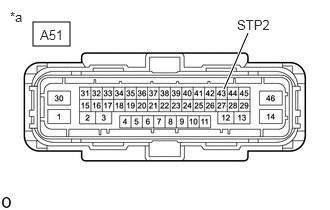
| *a | Front view of wire harness connector
(to Skid Control ECU (Brake Actuator Assembly)) |
Make sure that there is no looseness at the locking part and the connecting part of the connectors.
- OK:
The connector is securely connected.
Disconnect the A51 skid control ECU (brake actuator assembly) connector.
Check both the connector case and the terminals for deformation and corrosion.
- OK:
No deformation or corrosion.
Measure the voltage according to the value(s) in the table below.
- Standard Voltage:
Tester Connection Condition Specified Condition A51-43 (STP2) - Body ground Brake pedal depressed 11 to 14 V
- Result:
Proceed to OK NG
OK
NG
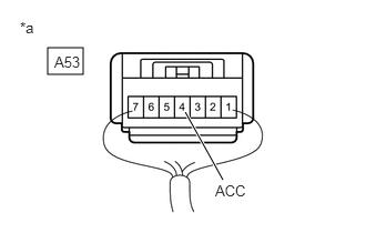
| *a | Component with harness connected
(Stop Light Switch Assembly) |
Make sure that there is no looseness at the locking part and the connecting part of the connector.
- OK:
The connector is securely connected.
Measure the voltage according to the value(s) in the table below.
- Standard Voltage:
Tester Connection Condition Specified Condition A53-4 (ACC) - Body ground Always 11 to 14 V
- Result:
Proceed to OK NG
OK
NG
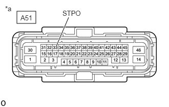
| *a | Front view of wire harness connector
(to Skid Control ECU (Brake Actuator Assembly)) |
Make sure that there is no looseness at the locking part and the connecting part of the connectors.
- OK:
The connector is securely connected.
Disconnect the A51 skid control ECU (brake actuator assembly) connector.
Check both the connector case and the terminals for deformation and corrosion.
- OK:
No deformation or corrosion.
Measure the voltage according to the value(s) in the table below.
- Standard Voltage:
Tester Connection Condition Specified Condition A51-33 (STPO) - Body ground Brake pedal depressed 11 to 14 V
- Result:
Proceed to OK NG
OK
NG
Make sure that there is no looseness at the locking part and the connecting part of the connectors.
- OK:
The connector is securely connected.
Disconnect the A51 skid control ECU (brake actuator assembly) connector.
Check both the connector case and the terminals for deformation and corrosion.
- OK:
No deformation or corrosion.
Check that the stop lights come on when the brake pedal is depressed.
- OK:
The stop lights illuminate.
- Result:
Proceed to OK NG
OK
NG
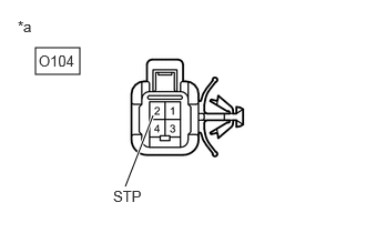
| *a | Front view of wire harness connector
(to Rear Combination Light Assembly LH) |
Make sure that there is no looseness at the locking part and the connecting part of the connectors.
- OK:
The connector is securely connected.
Disconnect the A51 skid control ECU (brake actuator assembly) connector.
Disconnect the O104 rear combination light assembly LH connector.
Check both the connector case and the terminals for deformation and corrosion.
- OK:
No deformation or corrosion.
Measure the voltage according to the value(s) in the table below.
- Standard Voltage:
Tester Connection Condition Specified Condition O104-2 (STP) - Body ground Brake pedal depressed 11 to 14 V
- Result:
Proceed to OK NG
OK
Refer to "Left or right stop light does not illuminate" of problem symptoms table.
NG

| *a | Front view of wire harness connector
(to Rear Combination Light Assembly RH) |
Make sure that there is no looseness at the locking part and the connecting part of the connectors.
- OK:
The connector is securely connected.
Disconnect the A51 skid control ECU (brake actuator assembly) connector.
Disconnect the O104 rear combination light assembly LH connector.
Disconnect the O103 rear combination light assembly RH connector.
Check both the connector case and the terminals for deformation and corrosion.
- OK:
No deformation or corrosion.
Measure the voltage according to the value(s) in the table below.
- Standard Voltage:
Tester Connection Condition Specified Condition O103-2 (STP) - Body ground Brake pedal depressed 11 to 14 V
- Result:
Proceed to OK NG
OK
Refer to "Left or right stop light does not illuminate" of problem symptoms table.
NG
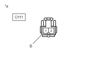
| *a | Front view of wire harness connector
(to Center Stop Light Set) |
Make sure that there is no looseness at the locking part and the connecting part of the connectors.
- OK:
The connector is securely connected.
Disconnect the A51 skid control ECU (brake actuator assembly) connector.
Disconnect the O104 rear combination light assembly LH connector.
Disconnect the O103 rear combination light assembly RH connector.
Disconnect the O111 center stop light set connector.
Check both the connector case and the terminals for deformation and corrosion.
- OK:
No deformation or corrosion.
Measure the voltage according to the value(s) in the table below.
- Standard Voltage:
Tester Connection Condition Specified Condition O111-1 (B) - Body ground Brake pedal depressed 11 to 14 V
- Result:
Proceed to OK NG
OK
NG
Make sure that there is no looseness at the locking part and the connecting part of the connectors.
- OK:
The connector is securely connected.
Disconnect the A51 skid control ECU (brake actuator assembly) connector.
Disconnect the O104 rear combination light assembly LH connector.
Disconnect the O103 rear combination light assembly RH connector.
Disconnect the O111 center stop light set connector.
Disconnect the A53 stop light switch assembly connector.
Check both the connector case and the terminals for deformation and corrosion.
- OK:
No deformation or corrosion.
Measure the resistance according to the value(s) in the table below.
- Standard Resistance:
Tester Connection Condition Specified Condition A53-1 (OUT) - O104-2 (STP) Always Below 1 Ω A53-1 (OUT) or O104-2 (STP) - Body ground Always 10 kΩ or higher
- Result:
Proceed to OK NG
OK
NG