TELEMATICS TELEMATICS SYSTEM(for Gasoline Model) TERMINALS OF ECU
TELEMATICS TRANSCEIVER (for 10.25 Inch Display)
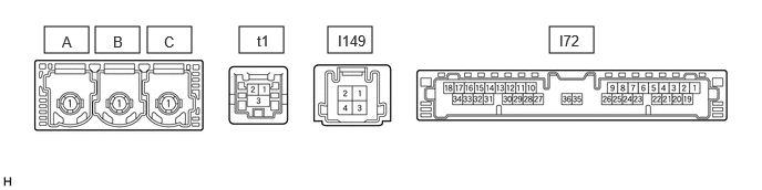
| Terminal No. (Symbol) | Terminal Description | Condition | Specified Condition |
|---|---|---|---|
| I72-1 (+B) - I72-20 (E) | Power source (+B) | Always | 11 to 14 V |
| I72-3 (SIG-) - I72-20 (E) | Ground | Always | Below 1 V |
| I72-4 (IND1) - I72-20 (E) | Emergency call switch red indicator illumination signal | For 5 seconds after turning the engine switch on (IG) | 1 to 8.5 V |
| Engine switch off | Below 1 V | ||
| I72-5 (MCVD) - I72-20 (E) | Telephone microphone assembly power supply | Engine switch on (IG) | 7.5 to 8.5 V |
| Engine switch off | Below 1 V | ||
| I72-6 (MCI+) - I72-20 (E) | Microphone voice signal | Voice being input to telephone microphone assembly | A waveform synchronized with microphone voice signal is input |
| I72-7 (MCI-) - I72-20 (E) | Microphone voice signal | Always | Below 1 V |
| I72-13 (GSW) - I72-20 (E) | Collision detection signal | Engine switch on (IG) | Pulse generation (Refer to waveform 1) |
| I72-14 (MUTE) - I72-20 (E) | MUTE Signal | Audio system playing | Above 3.5 V |
| Emergency call mode | Below 1 V | ||
| I72-15 (USBV) - I72-20 (E) | Telephone microphone assembly power supply | Engine switch on (IG) | 4.75 to 5.25 V |
| Engine switch off | Below 1 V | ||
| I72-16 (MCO+) - I72-20 (E) | Microphone voice signal | Voice being input to telephone microphone assembly | A waveform synchronized with microphone voice signal is input |
| I72-17 (VOT+) - I72-20 (E)* | Sent voice signal | Calling while using the operator service | A waveform synchronized with the received voice is output |
| I72-19 (IG2) - I72-20 (E) | Power source (IG) | Engine switch on (IG) | 11 to 14 V |
| Engine switch off | Below 1 V | ||
| I72-20 (E) - Body ground | Ground | Always | Below 1 V |
| I72-21 (SIG1) - I72-3 (SIG-) | Emergency call switch button condition signal | Emergency call switch not pressed | 1.3 to 1.9 V |
| Emergency call switch pressed | 0.5 to 0.8 V | ||
| I72-22 (IND2) - I72-20 (E) | Emergency call switch green indicator illumination signal | For 5 seconds after turning the engine switch on (IG) | 1 to 8.5 V |
| Engine switch off | Below 1 V | ||
| I72-23 (SGND) - I72-20 (E) | Shield ground | Always | Below 1 V |
| I72-25 (CANP) | CAN communication signal | - | - |
| I72-26 (CANN) | CAN communication signal | - | - |
| I72-31 (USBG) - Body ground | Shield ground | Always | Below 1 V |
| I72-32 (MCO-) - I72-20 (E) | Microphone voice signal | Always | Below 1 V |
| I72-33 (VOT-) - I72-20 (E)* | Sent voice signal | Calling while using the operator service | A waveform synchronized with the received voice is output |
| I149-1 (SPI+) - I72-20 (E) | Sound signal | Audio system playing | A waveform synchronized with sound signals is output |
| I149-2 (SPI-) - I72-20 (E) | Sound signal | Audio system playing | A waveform synchronized with sound signals is output |
| I149-3 (SPO+) - I72-20 (E) | Sound signal | Emergency call mode | A waveform synchronized with the received voice is output |
| I149-4 (SPO-) - I72-20 (E) | Sound signal | Emergency call mode | A waveform synchronized with the received voice is output |
| t1-1 (USB-) | USB communication line | - | - |
| t1-2 (USB+) | USB communication line | - | - |
| t1-3 (USBS) - Body ground | Shield ground | Always | Below 1 V |
*: for Navigation Receiver Type
TELEMATICS TRANSCEIVER (except 10.25 Inch Display)
| Terminal No. (Symbol) | Terminal Description | Condition | Specified Condition |
|---|---|---|---|
| I72-1 (+B) - I72-20 (E) | Power source (+B) | Always | 11 to 14 V |
| I72-3 (SIG-) - I72-20 (E) | Ground | Always | Below 1 V |
| I72-4 (IND1) - I72-20 (E) | Emergency call switch red indicator illumination signal | For 5 seconds after turning the engine switch on (IG) | 1 to 8.5 V |
| Engine switch off | Below 1 V | ||
| I72-5 (MCVD) - I72-20 (E) | Telephone microphone assembly power supply | Engine switch on (IG) | 4 to 6 V*3
7.5 to 8.5 V*4 |
| Engine switch off | Below 1 V | ||
| I72-6 (MCI+) - I72-20 (E) | Microphone voice signal | Voice being input to telephone microphone assembly | A waveform synchronized with microphone voice signal is input |
| I72-7 (MCI-) - I72-20 (E) | Microphone voice signal | Always | Below 1 V |
| I72-13 (GSW) - I72-20 (E) | Collision detection signal | Engine switch on (IG) | Pulse generation (Refer to waveform 1) |
| I72-14 (MUTE) - I72-20 (E) | MUTE Signal | Audio system playing | Above 3.5 V |
| Emergency call mode | Below 1 V | ||
| I72-15 (USBV) - I72-20 (E)*1 | Telephone microphone assembly power supply | Engine switch on (IG) | 4.75 to 5.25 V |
| Engine switch off | Below 1 V | ||
| I72-16 (MCO+) - I72-20 (E) | Microphone voice signal | Voice being input to telephone microphone assembly | A waveform synchronized with microphone voice signal is input |
| I72-17 (VOT+) - I72-20 (E)*1*4 | Sent voice signal | Calling while using the operator service | A waveform synchronized with the received voice is output |
| I72-19 (IG2) - I72-20 (E) | Power source (IG) | Engine switch on (IG) | 11 to 14 V |
| Engine switch off | Below 1 V | ||
| I72-20 (E) - Body ground | Ground | Always | Below 1 V |
| I72-21 (SIG1) - I72-3 (SIG-) | Emergency call switch button condition signal | Emergency call switch not pressed | 1.3 to 1.9 V |
| Emergency call switch pressed | 0.5 to 0.8 V | ||
| I72-22 (IND2) - I72-20 (E) | Emergency call switch green indicator illumination signal | For 5 seconds after turning the engine switch on (IG) | 1 to 8.5 V |
| Engine switch off | Below 1 V | ||
| I72-23 (SGND) - I72-20 (E) | Shield ground | Always | Below 1 V |
| I72-25 (CANP) | CAN communication signal | - | - |
| I72-26 (CANN) | CAN communication signal | - | - |
| I72-31 (USBG) - Body ground*1 | Shield ground | Always | Below 1 V |
| I72-32 (MCO-) - I72-20 (E) | Microphone voice signal | Always | Below 1 V |
| I72-33 (VOT-) - I72-20 (E)*1*4 | Sent voice signal | Calling while using the operator service | A waveform synchronized with the received voice is output |
| I149-1 (SPI+) - I72-20 (E) | Sound signal | Audio system playing | A waveform synchronized with sound signals is output |
| I149-2 (SPI-) - I72-20 (E) | Sound signal | Audio system playing | A waveform synchronized with sound signals is output |
| I149-3 (SPO+) - I72-20 (E) | Sound signal | Emergency call mode | A waveform synchronized with the received voice is output |
| I149-4 (SPO-) - I72-20 (E) | Sound signal | Emergency call mode | A waveform synchronized with the received voice is output |
| I72-30 (SLPD) - I72-20 (E)*2 | Steering lock bar position signal | Steering locked | 11 to 14 V |
| Steering unlocked | Below 1.5 V | ||
| t1-1 (USB-)*1 | USB communication line | - | - |
| t1-2 (USB+)*1 | USB communication line | - | - |
| t1-3 (USBS) - Body ground*1 | Shield ground | Always | Below 1 V |
*1: for Navigation Receiver Type
*2: w/ Remote Engine Starter
*3: except 9inch Display without RST Switch
*4: for 9inch Display without RST Switch
RADIO AND DISPLAY RECEIVER ASSEMBLY (w/o Navigation System)
except 10.25 Inch Display: Click hereAudio / Visual / Telematics>AUDIO / VIDEO>AUDIO AND VISUAL SYSTEM (for Gasoline Model with Radio and Display Type (except 10.25 Inch Display))>TERMINALS OF ECU202205,999999,_56,_080751,_0392314,RM1000000023AZ4,
for 10.25 Inch Display: Click hereAudio / Visual / Telematics>AUDIO / VIDEO>AUDIO AND VISUAL SYSTEM (for 10.25 Inch Display)>TERMINALS OF ECU202304,999999,_56,_080751,_0599626,RM100000002B8WK,
NAVIGATION RECEIVER ASSEMBLY (w/ Navigation System)
for 9 Inch Display with RST Switch: Click hereAudio / Visual / Telematics>NAVIGATION / MULTI INFO DISPLAY>NAVIGATION SYSTEM (for Gasoline Model with RST Switch)>TERMINALS OF ECU202104,999999,_56,_080752,_0391865,RM100000001WIVD,
for 9 Inch Display without RST Switch: Click hereAudio / Visual / Telematics>NAVIGATION / MULTI INFO DISPLAY>NAVIGATION SYSTEM (w/o RST Switch (except 10.25 Inch Display))>TERMINALS OF ECU202205,999999,_56,_080752,_0528911,RM1000000022MWO,
for 10.25 Inch Display: Click hereAudio / Visual / Telematics>NAVIGATION / MULTI INFO DISPLAY>NAVIGATION SYSTEM (for 10.25 Inch Display)>TERMINALS OF ECU202304,202307,_56,_080752,_0599611,RM100000002BDIZ,202307,999999,_56,_080752,_0599611,RM100000002D1NU,