AUDIO / VIDEO AUDIO AND VISUAL SYSTEM(for Gasoline Model with Radio and Display Type (except 10.25 Inch Display)) TERMINALS OF ECU
- HINT:
-
Check from the rear of the connector while it is connected to the components.
RADIO AND DISPLAY RECEIVER ASSEMBLY
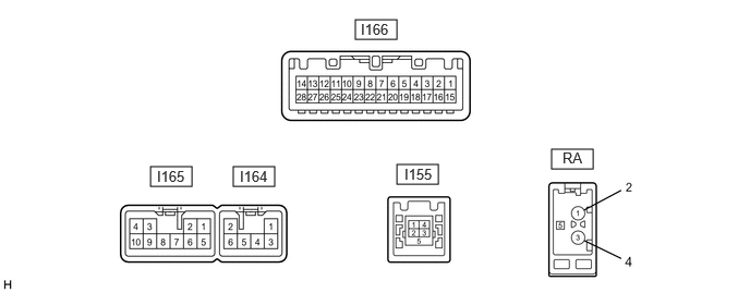
| Terminal No. (Symbol) | Terminal Description | Condition | Specified Condition |
|---|---|---|---|
| I165-1 (FR+) - I165-7 (GND1) | Sound signal (Front right) | Audio system playing | A waveform synchronized with sound signals is output |
| I165-2 (FL+) - I165-7 (GND1) | Sound signal (Front left) | Audio system playing | A waveform synchronized with sound signals is output |
| I165-3 (ACC1) - I165-7 (GND1) | Power source (ACC) | Engine switch off | Below 1 V |
| Engine switch on (ACC) | 10.5 to 16 V*2
11 to 14 V*3 |
||
| I165-4 (+B1) - I165-7 (GND1) | Power source (+B) | Engine switch off | 10.5 to 16 V*2
11 to 14 V*3 |
| I165-5 (FR-) - I165-7 (GND1) | Sound signal (Front right) | Audio system playing | A waveform synchronized with sound signals is output |
| I165-6 (FL-) - I165-7 (GND1) | Sound signal (Front left) | Audio system playing | A waveform synchronized with sound signals is output |
| I165-7 (GND1) - Body ground | Ground | Always | Below 1 V |
| I165-8 (TMUT) - I165-7 (GND1) | Mute signal | Audio system playing | Above 2.0 V |
| Emergency call mode | Below 1 V | ||
| I165-10 (ILL+) - I165-7 (GND1) | Illumination signal | Light control switch off | Below 1 V |
| Light control switch in tail or head position | 11 to 14 V | ||
| I164-1 (RR+) - I165-7 (GND1) | Sound signal (Rear right) | Audio system playing | A waveform synchronized with sound signals is output |
| I164-2 (RL+) - I165-7 (GND1) | Sound signal (Rear left) | Audio system playing | A waveform synchronized with sound signals is output |
| I164-3 (RR-) - I165-7 (GND1) | Sound signal (Rear right) | Audio system playing | A waveform synchronized with sound signals is output |
| I164-6 (RL-) - I165-7 (GND1) | Sound signal (Rear left) | Audio system playing | A waveform synchronized with sound signals is output |
| I166-1 (IG) - I165-7 (GND1) | Power source (IG) | Engine switch off | Below 1 V |
| Engine switch on (IG) | 11 to 14 V | ||
| I166-2 (REV) - I165-7 (GND1)*6 | Reverse signal | Engine switch on (IG)
Shift lever not in R |
Below 1 V |
| Engine switch on (IG)
Shift lever in R |
11 to 14 V | ||
| I166-2 (CSWA) - I165-7 (GND1)*7 | Reverse signal | Engine switch on (IG)
Shift lever not in R |
Below 1 V |
| Engine switch on (IG)
Shift lever in R |
11 to 14 V | ||
| I166-5 (MIN+) - I165-7 (GND1) | Microphone voice signal | Engine switch on (ACC) | A waveform synchronized with sound signals is output |
| I166-6 (SNS2) - I165-7 (GND1)*6 | Microphone connection detection signal | Microphone connection detection signal line connected | Below 1 V |
| Microphone connection detection signal line disconnected | 4.75 to 5.25 V | ||
| I166-6 (SNS) - I165-7 (GND1)*7 | Microphone connection detection signal | Microphone connection detection signal line connected | Below 1 V |
| Microphone connection detection signal line disconnected | 4.75 to 5.25 V | ||
| I166-13 (CA+) - I165-7 (GND1) | Television camera power supply | Engine switch on (ACC) | 5.8 to 6.5 V*4
2.5 to 3.3 V*5 |
| I166-14 (V+) - I165-7 (GND1) | Video signal | Engine switch on (IG)
Shift lever in R Camera lens not covered, displaying an image |
Pulse generation
(Refer to waveform 1) |
| Engine switch on (IG)
Shift lever in R Camera lens covered, blacking out screen |
Pulse generation
(Refer to waveform 2) |
||
| I166-15 (PKB) - I165-7 (GND1) | Parking brake signal | Engine switch on (IG)
Parking brake released |
11 to 14 V |
| Engine switch on (IG)
Parking brake applied |
Below 1 V | ||
| I166-17 (SPD) - I165-7 (GND1) | Vehicle speed signal | Vehicle driving | Pulse generation |
| I166-18 (SGND) - Body ground | Shield ground | Always | Below 1 V |
| I166-19 (MIN-) - I165-7 (GND1) | Microphone voice signal | Always | Below 1 V |
| I166-21 (SW1) - I166-23 (SWG)*1 | Steering pad switch signal | No switch pushed | 2.90 to 3.34 V*5
3.20 to 3.34 V*4 |
| Seek+ switch pushed | 0.39 to 0.86 V*5
0.55 to 0.70 V*4 |
||
| Seek- switch pushed | 0.87 to 1.48 V*5
1.11 to 1.29 V*4 |
||
| Volume+ switch pushed | 1.49 to 2.16 V*5
1.75 to 1.90 V*4 |
||
| Volume- switch pushed | 2.17 to 2.89 V*5
2.50 to 2.63 V*4 |
||
| I166-22 (SW2) - I166-23 (SWG)*1 | Steering pad switch signal | No switch pushed | 2.90 to 3.34 V*5
3.20 to 3.34 V*4 |
| MODE/HOLD switch pushed | 0.39 to 0.86 V*5
0.55 to 0.70 V*4 |
||
| Telephone switch pushed | 0.87 to 1.48 V*5
1.11 to 1.29 V*4 |
||
| Voice switch pushed | 2.17 to 2.89 V*5
2.50 to 2.63 V*4 |
||
| I166-23 (SWG) - I165-7 (GND1)*1 | Steering pad switch ground | Always | Below 1 V |
| I166-27 (CGND) - Body ground | Shield ground | Always | Below 1 V |
| I166-28 (V-) - I165-7 (GND1) | Ground | Always | Below 1 V |
| RA-5 (ANT+) - I165-7 (GND1) | Power source of antenna | Engine switch on (ACC)
Radio switch on and FM selected |
11 to 14 V |
*1: w/ Steering Pad Switch Assembly
*2: w/ Stop and Start System
*3: w/o Stop and Start System
*4: w/o "Apple CarPlay" Function
*5: w/ "Apple CarPlay" Function
*6: except ALLION
*7: for ALLION
Reference (Oscilloscope waveform):
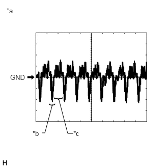
| *a | Waveform 1 (camera lens not covered, displaying an image) |
| *b | Synchronization Signal |
| *c | Video Waveform |
Waveform 1 (camera lens not covered, displaying an image)
| Item | Content |
|---|---|
| Measurement terminal | I166-14 (V+) - I165-7 (GND1) |
| Measurement setting | 200 mV/DIV., 50 μs/DIV. |
| Condition | Engine switch on (IG), shift lever in R |
- HINT:
- ·
The video waveform changes according to the image sent by the rear television camera assembly.
·The video waveform is constantly output when the engine switch is turned on (ACC).
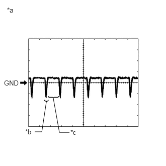
| *a | Waveform 2 (camera lens covered, blacking out the screen) |
| *b | Synchronization Signal |
| *c | Video Waveform |
Waveform 2 (camera lens covered, blacking out the screen)
| Item | Content |
|---|---|
| Measurement terminal | I166-14 (V+) - I165-7 (GND1) |
| Measurement setting | 200 mV/DIV., 50 μs/DIV. |
| Condition | Engine switch on (IG), shift lever in R |
- HINT:
- ·
The video waveform changes according to the image sent by the rear television camera assembly.
·The video waveform is constantly output when the engine switch is turned on (ACC).
COMBINATION METER ASSEMBLY
REAR TELEVISION CAMERA ASSEMBLY