NAVIGATION / MULTI INFO DISPLAY NAVIGATION SYSTEM(for 10.25 Inch Display) TERMINALS OF ECU
RADIO AND DISPLAY RECEIVER ASSEMBLY
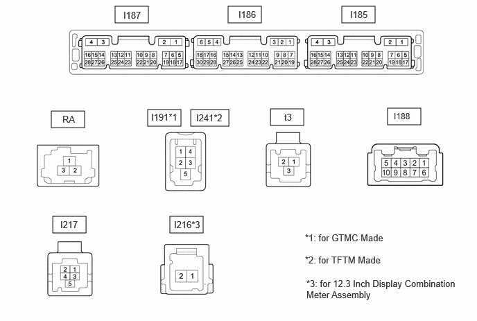
| Terminal No. (Symbol) | Terminal Description | Condition | Specified Condition |
|---|---|---|---|
|
*: w/ Panoramic View Monitor System |
|||
| I187-1 (GND1) - Body ground | Ground | Always | Below 1 Ω |
| I187-2 (GND2) - Body ground | Ground | Always | Below 1 Ω |
| I187-3 (+B) - I187-1 (GND1) | Power source (+B) | Ignition switch off | 10.5 to 16 V |
| I187-4 (+B1) - I187-1 (GND1) | Power source (+B) | Ignition switch off | 10.5 to 16 V |
| I187-5 (REV) - I187-1 (GND1) | Reverse Signal | Ignition switch ON, shift position not in R → shift position in R | 2 V or less → 11 to 14 V |
| I187-7 (PKB) - I187-1 (GND1) | Parking brake signal | Ignition switch ON
Parking brake released → Ignition switch ON Parking brake applied |
2 V or less → 3 V or higher |
| I187-8 (SPD) - I187-1 (GND1) | Vehicle speed signal | Wheel being rotated | Waveform 1 |
| I187-15 (IG) - I187-1 (GND1) | Power source (IG) | Ignition switch ON | 11 to 14 V |
| I187-16 (ACC1) - I187-1 (GND1) | Power source (ACC) | Ignition switch ACC | 11 to 14 V |
| I187-17(REVD) - I187-1(GND1) | Camera image transition signal | Normal → camera image screen change | 2 V or less → 6 V or higher |
| I187-19 (CSW+) - I187-1 (GND1)* | Camera image transition signal | Normal → camera image screen change | 2 V or less → 6 V or higher |
| I187-20 (SWG) - I187-1 (GND1) | Ground | Always | Below 1 Ω |
| I187-21 (SW1) - I187-1 (GND1) | Steering pad switch signal | No switch pushed → Volume- switch pushed → Volume+ switch pushed → Seek- switch pushed → Seek+ switch pushed | 2.7 V or higher → approximately 2.3 V → approximately 1.6 V → approximately 1.0 V → 0.8 V or less |
| I187-22 (SW2) - I187-1 (GND1) | Steering pad switch signal | No switch pushed → Voice switch pushed → Off hook switch pushed → On hook switch pushed → MODE switch pushed | 2.7 V or higher → approximately 2.3 V → approximately 1.6 V → approximately 1.0 V → 0.8 V or less |
| I187-25 (ILL+) - I187-1 (GND1) | Illumination signal | Ignition switch ON, light control switch in tail or head position | 11 to 14 V |
| I187-28 (ACCO) - I187-1 (GND1) | Multimedia ACC controlsignal | Power switch is pressed when playback is starting | 8.0 to 13.5 V |
| Terminal No. (Symbol) | Terminal Description | Condition | Specified Condition |
|---|---|---|---|
|
*1: except M15C-FKS, 8ZR-FXE GTMC Made *2: for M15C-FKS, 8ZR-FXE GTMC Made |
|||
| I186-4(SGND) - I187-1(GND1) | Shield ground | Always | Below 1 Ω |
| I186-5 (TMUT) - I187-1 (GND1) | Mute signal | Normal → Emergency call mode | 2.0 V or higher → Below 1 V |
| I186-6 (ADPG) - I187-1 (GND1) | No. 1 stereo jack adapter assembly detection signal | No. 1 stereo jack adapter assembly disconnected → No. 1 stereo jack adapter assembly connected | 3.3 V or higher→ Below 2.15 V |
| I186-11 (CNH1) | Local bus communication signal | Service Menu | - |
| I186-12 (CNL1) | Local bus communication signal | Service Menu | - |
| I186-13 (CANH) | CAN communication signal | Service Menu | - |
| I186-14 (CANL) | CAN communication signal | Service Menu | - |
| I186-15 (VOR+) - I187-1(GND1) | Sound signal | Answering incomingoperator call | A waveform synchronizedwith sound signals isoutput |
| I186-16 (VOR-) - I187-1(GND1) | Sound signal | Answering incomingoperator call | A waveform synchronizedwith sound signals isoutput |
| I186-17 (USBG) - Body ground | Ground | Always | Below 1 Ω |
| I186-18 (USBV) - I187-1 (GND1) | Telematics transceiver USB power source | Ignition switch ON | 3 V or higher |
| I186-21 (MIN+) - I187-1 (GND1) | Microphone voice signal | Voice is being input | A waveform synchronized with sound signals is output |
| I186-22 (MIN-) - I187-1 (GND1) | Microphone voice signal ground | Always | Below 1 Ω |
| I186-24 (SGND) - Body ground | Shield ground | Always | Below 1 Ω |
| I186-25 (SNS) - I187-1 (GND1)*1 | Microphone circuit open detection signal | Always | Below 1 Ω |
| I186-25 (SNS1) - I187-1 (GND1)*2 | Microphone circuit open detection signal | Always | Below 1 Ω |
| Terminal No. (Symbol) | Terminal Description | Condition | Specified Condition |
|---|---|---|---|
| I185-17 (MI2+) - I187-1 (GND1) | Microphone 2 voice signal | Voice is being input | A waveform synchronizedwith sound signals isoutput |
| I185-18 (MI2-) - I187-1 (GND1) | Microphone 2 voice signal ground | Always | Below 1 Ω |
| I185-19 (SGD2) - I187-1 (GND1) | Ground | Always | Below 1 Ω |
| I185-20 (MAC2) - I187-1 (GND1) | Microphone 2 powersource | Ignition switch ON | 7.5 to 8.5 V |
| I185-21 (SNS2) - I187-1 (GND1) | Microphone 2 open circuitdetection signal | Always | Below 1 Ω |
| Terminal No. (Symbol) | Terminal Description | Condition | Specified Condition |
|---|---|---|---|
| I188-1 (FR+) - I187-1 (GND1) | Sound signal | Audio system playing | A waveform synchronized with sound signals is output |
| I188-2 (FL+) - I187-1 (GND1) | Sound signal | Audio system playing | A waveform synchronized with sound signals is output |
| I188-3 (RL+) - I187-1 (GND1) | Sound signal | Audio system playing | A waveform synchronized with sound signals is output |
| I188-4 (RR+) - I187-1 (GND1) | Sound signal | Audio system playing | A waveform synchronized with sound signals is output |
| I188-6 (FR-) - I187-1 (GND1) | Sound signal | Audio system playing | A waveform synchronized with sound signals is output |
| I188-7 (FL-) - I187-1 (GND1) | Sound signal | Audio system playing | A waveform synchronized with sound signals is output |
| I188-8 (RL-) - I187-1 (GND1) | Sound signal | Audio system playing | A waveform synchronized with sound signals is output |
| I188-9 (RR-) - I187-1 (GND1) | Sound signal | Audio system playing | A waveform synchronized with sound signals is output |
| Terminal No. (Symbol) | Terminal Description | Condition | Specified Condition |
|---|---|---|---|
| t3-1 (USB+) | USB communication signal | - | - |
| t3-2 (USB-) | USB communication signal | - | - |
| t3-3 (USBS) | USB communication signal | - | - |
| Terminal No. (Symbol) | Terminal Description | Condition | Specified Condition |
|---|---|---|---|
| I191-1 (USV1) | Power source | Ignition switch ON | 4.75 to 5.25 V |
| I191-2 (US1-) | USB communication signal | - | - |
| I191-3 (US1+) | USB communication signal | - | - |
| I191-4 (UGD1) | Ground | Always | Below 1 Ω |
| I191-5 (USG1) | Shield ground | Always | Below 1 Ω |
| Terminal No. (Symbol) | Terminal Description | Condition | Specified Condition |
|---|---|---|---|
| I241-1 (USV1) | Power source | Ignition switch ON | 4.75 to 5.25 V |
| I241-2 (US1-) | USB communication signal | - | - |
| I241-3 (US1+) | USB communication signal | - | - |
| I241-4 (UGD1) | Ground | Always | Below 1 Ω |
| I241-5 (USG1) | Shield ground | Always | Below 1 Ω |
| Terminal No. (Symbol) | Terminal No. (Symbol) | Condition | Specified Condition |
|---|---|---|---|
| I217-1 (CGND) - I187-1 (GND1) | Camera Ground | Always | Below 1 Ω |
| I217-2 (CB+) - I217-1 (CGND) | Camera power source | Ignition switch ON | Below 1 Ω |
| I217-3 (CV+) | Video Signal | - | - |
| I217-4 (CV-) | Video Signal | - | - |
| I217-5 (SGND) - I187-1 (GND1) | Shield ground | Always | Below 1 Ω |
| Terminal No. (Symbol) | Terminal No. (Symbol) | Condition | Specified Condition |
|---|---|---|---|
| I217-1 (GGND) - I187-1 (GND1) | Camera Ground | Always | Below 1 Ω |
| I217-2 (GB+) - I217-1 (GGND) | Camera power source | Ignition switch ON | Below 1 Ω |
| I217-3 (GVO+) | Video Signal | - | - |
| I217-4 (GVO-) | Video Signal | - | - |
| I217-5 (SGND) - I187-1 (GND1) | Shield ground | Always | Below 1 Ω |
| Terminal No. (Symbol) | Terminal Description | Condition | Specified Condition |
|---|---|---|---|
| I216-1(ETH-) | Ethernet communication signal | - | - |
| I216-2(ETH+) | Ethernet communication signal | - | - |
| Terminal No. (Symbol) | Terminal Description | Condition | Specified Condition |
|---|---|---|---|
| RA-1 (ANT+) | Radio antenna power source | Receiving radio broadcast | 7 to 16 V |
| RA-3 (MAIN) | Radio signal (MAIN) | - | - |
| RA-3a (GND) | Ground | - | - |
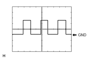
Waveform 1
| Item | Content |
|---|---|
| Measurement terminal | I187-8 (SPD) - I187-1 (GND1) |
| Measurement setting | 5 V/DIV, 20 ms/DIV |
| Condition | Wheel being rotated |
- HINT:
-
The period changes depending on the rotation speed of the wheels.
TELEMATICS TRANSCEIVER
COMBINATION METER ASSEMBLY
- HINT:
-
for 12.3 Inch Display: Click hereVehicle Interior>METER / GAUGE / DISPLAY>METER / GAUGE SYSTEM (for 12.3 Inch Display)>TERMINALS OF ECU202307,202406,_58,_080793,_0473175,RM100000002D0F5,202406,999999,_58,_080793,_0473175,RM100000002NEI0,
-
except 12.3 Inch Display: Click hereVehicle Interior>METER / GAUGE / DISPLAY>METER / GAUGE SYSTEM (except 12.3 Inch Display)>TERMINALS OF ECU202307,202406,_58,_080793,_0598151,RM100000002D0G4,202406,202502,_58,_080793,_0598151,RM100000002NEI1,202502,999999,_58,_080793,_0598151,RM100000002RNOV,