THEFT DETERRENT / KEYLESS ENTRY SMART ENTRY AND START SYSTEM(for Start Function, Gasoline Model (NR Series)) Engine does not Start
DESCRIPTION
When the electrical key transmitter sub-assembly is in the cabin and the engine switch is pressed, the certification ECU (smart key ECU assembly) receives a signal and changes the power source mode. Additionally, when the shift lever is in P and the brake pedal is depressed, the engine can be started by pressing the engine switch.
| Problem Symptom | Data List and Active Test |
|---|---|
| Engine does not start | Power Source Control
·
Stop Light Switch1 ·
Steering Unlock Switch ·
Shift P Signal ·
Neutral SW/ Clutch SW ·
IG Relay Monitor (Inside) ·
IG Relay Monitor (Outside) ·
Latch Circuit ·
Starter Request Signal ·
Power Supply Condition Entry&Start
·
Immobiliser ·
Engine Start Request ·
S Code Check ·
L Code Check Starting Control
·
Starter SW ·
Shift Position P or N ·
Ignition |
WIRING DIAGRAM
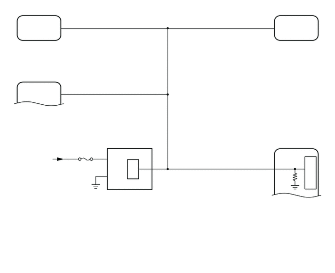
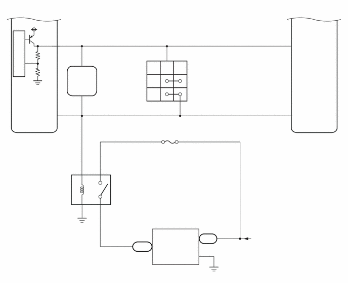
CAUTION / NOTICE / HINT
- NOTICE:
- ·
When using the GTS with the engine switch off, connect the GTS to the DLC3 and turn a courtesy light switch on and off at intervals of 1.5 seconds or less until communication between the GTS and the vehicle begins. Then select Model Code "KEY REGIST" under manual mode and enter the following menus: Body Electrical / Entry&Start(CAN). While using the GTS, periodically turn a courtesy light switch on and off at intervals of 1.5 seconds or less to maintain communication between the GTS and the vehicle.
·The smart entry and start system (for Start Function) uses the LIN communication system and CAN communication system. Inspect the communication function by following How to Proceed with Troubleshooting. Troubleshoot the smart entry and start system (for Start Function) after confirming that the communication systems are functioning properly.
·If the smart entry and start system (for Start Function) has been disabled, enable the system before performing troubleshooting.
·Inspect the fuses for circuits related to this system before performing the following procedure.
·Before replacing the certification ECU (smart key ECU assembly) or an electrical key transmitter sub-assembly, refer to Service Bulletin.
·After completing repairs, confirm that the problem does not recur.
·After performing repairs, confirm that no DTCs are output by performing "DTC Output Confirmation Operation."
- HINT:
- ·
If interior verification is unsuccessful, Operation History may be stored.
·If Operation History has been stored, refer to the Operation History List to determine the detection conditions and narrow down trouble areas.
- Body Electrical > Entry&Start > Utility
-
Tester Display Operation History - 50005 125 52
PROCEDURE
Check that the engine starts.
- OK:
Engine starts normally.
- Result:
Proceed to OK NG
OK
NG
Turn the engine switch off.
When the immobiliser is set, check that the security indicator light blinks.
Turn the engine switch on (IG).
When the immobiliser is unset, check that the security indicator light turns off.
- OK:
The security indicator light operates normally.
- Result:
Proceed to OK NG
OK
NG
Check for DTCs.
- Body Electrical > Entry&Start > Trouble Codes
- 50001 125
- OK:
LIN communication system DTC B2785 or B2789 is not output simultaneously.
- Result:
Proceed to OK NG
OK
NG
Get into the vehicle while carrying an electrical key transmitter sub-assembly.
Move the shift lever to P.
Depress the brake pedal.
Check that the key indicator display is displayed on the multi-information display in the combination meter assembly, and then press the engine switch and check that the engine cranks.
- Result:
Result Proceed to Engine cranks and initial combustion occurs A Engine cranks but initial combustion does not occur B Engine does not crank C
A
B
C
Get into the vehicle while carrying an electrical key transmitter sub-assembly.
Move the shift lever to P.
With the brake pedal released, check that pressing the engine switch causes the power source mode to change.
- Result:
Result Proceed to Power source mode changes : Off → on (ACC) → on (IG) → off A Power source mode does not change to on (ACC) or on (IG) B Power source mode changes to on (IG) but not to on (ACC) C Power source mode changes to on (ACC) but not to on (IG) D
A
B
C
D
Connect the GTS to the DLC3.
Turn the engine switch on (IG).
Turn the GTS on.
Enter the following menus: Body Electrical / Power Source Control / Data List.
Read the Data List according to the display on the GTS.
- Body Electrical > Power Source Control > Data List
-
Tester Display Measurement Item Range Normal Condition Diagnostic Note Stop Light Switch1 State of brake pedal OFF or ON OFF: Brake pedal released
ON: Brake pedal depressed·Use this item to determine if the stop light switch assembly is malfunctioning.
·The engine cannot be started when this item is OFF.
·If the stop light switch assembly is malfunctioning, the engine can be started by pressing and holding the engine switch for a certain period of time.
- Body Electrical > Power Source Control > Data List
-
Tester Display Stop Light Switch1 - 50003 223 3
- OK:
The GTS display changes correctly in response to the brake pedal operation.
- Result:
Proceed to OK NG
OK
NG
Enter the following menus: Body Electrical / Power Source Control or Starting Control / Data List.
Read the Data List according to the display on the GTS.
- Body Electrical > Power Source Control > Data List
-
Tester Display Measurement Item Range Normal Condition Diagnostic Note Neutral SW/ Clutch SW Shift position (P and N) OFF or ON OFF: Shift lever in any position other than P or N
ON: Shift lever in P or N·Use this item to determine if the park/neutral position switch assembly is malfunctioning.
·When the engine cannot be started due to a park/neutral position switch assembly malfunction, OFF is displayed.
- Body Electrical > Power Source Control > Data List
-
Tester Display Neutral SW/ Clutch SW - 50003 223 6
- Body Electrical > Starting Control > Data List
-
Tester Display Measurement Item Range Normal Condition Diagnostic Note Shift Position P or N Park/Neutral position switch status OFF or ON OFF: Shift lever not in P or N
ON: Shift lever in P or NWhen OFF is displayed, the engine will not crank.
- Body Electrical > Starting Control > Data List
-
Tester Display Shift Position P or N - 50003 221 2
- OK:
The GTS display changes correctly in response to the shift lever operation.
- Result:
Proceed to OK NG
OK
NG
Enter the following menus: Body Electrical / Power Source Control / Data List.
Read the Data List according to the display on the GTS.
- Body Electrical > Power Source Control > Data List
-
Tester Display Measurement Item Range Normal Condition Diagnostic Note Starter Request Signal Engine start request signal status OFF or ON OFF: The engine switch is not pressed
ON: With the shift lever in P and the brake pedal depressed, the engine switch is pressed and held·When the engine cannot be started due to a start request signal malfunction, OFF is displayed.
·When the engine switch is pressed, the duration of time that ON is displayed will be extremely short. As such, the engine switch needs to be pressed and held for a certain period of time.
- Body Electrical > Power Source Control > Data List
-
Tester Display Starter Request Signal - 50003 223 12
- NOTICE:
-
Check that the key indicator display is displayed on the multi-information display in the combination meter assembly, and then press the engine switch.
- OK:
The GTS display changes correctly in response to the engine switch operation.
- Result:
Proceed to OK NG
OK
NG
Get into the vehicle while carrying an electrical key transmitter sub-assembly.
Move the shift lever to P.
Enter the following menus: Body Electrical / Starting Control / Data List.
According to the display on the GTS, read the Data List while pressing the engine switch with the brake pedal depressed.
- Body Electrical > Starting Control > Data List
-
Tester Display Measurement Item Range Normal Condition Diagnostic Note Starter SW Starter operation request OFF or ON OFF: Starter operation not requested
ON: Starter operation requestedWhen OFF is displayed, the engine will not crank.
- Body Electrical > Starting Control > Data List
-
Tester Display Starter SW - 50003 221 1
- OK:
The GTS display changes.
- Result:
Proceed to OK NG
OK
NG
Inspect the ST relay.
- Result:
Proceed to OK NG
OK
NG
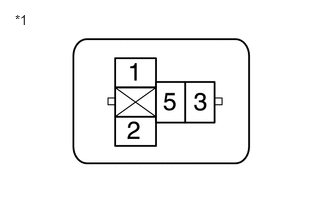
| *1 | NO. 1 ENGINE ROOM RELAY BLOCK AND NO. 1 JUNCTION BLOCK ASSEMBLY
(ST Relay Holder) |
Measure the voltage according to the value(s) in the table below.
- Standard Voltage:
Tester Connection Condition Specified Condition No. 1 engine room relay block and No. 1 junction block assembly ST relay terminal 1 - Body ground Engine switch pressed and held with brake pedal depressed (starter on) → Approximately 1 second after engine switch released (starter off) 6 V or higher* → 1.0 V or less
- HINT:
-
*: While the engine is cranking, the battery voltage may drop to approximately 6 V.
- Result:
Proceed to OK NG
OK
NG
| *1 | NO. 1 ENGINE ROOM RELAY BLOCK AND NO. 1 JUNCTION BLOCK ASSEMBLY
(ST Relay Holder) |
Measure the resistance according to the value(s) in the table below.
- Standard Resistance:
Tester Connection Condition Specified Condition No. 1 engine room relay block and No. 1 junction block assembly ST relay terminal 2 - Body ground Always Below 1 Ω
Measure the voltage according to the value(s) in the table below.
- Standard Voltage:
Tester Connection Condition Specified Condition No. 1 engine room relay block and No. 1 junction block assembly ST relay terminal 5 - Body ground Always 11 to 14 V
- Result:
Proceed to OK NG
OK
NG
Disconnect the C87 starter assembly connector.
Measure the resistance according to the value(s) in the table below.
- Standard Resistance:
Tester Connection Condition Specified Condition No. 1 engine room relay block and No. 1 junction block assembly ST relay terminal 3 - C87-2 Always Below 1 Ω No. 1 engine room relay block and No. 1 junction block assembly ST relay terminal 3 or C87-2 - Other terminals and body ground Always 10 kΩ or higher
- Result:
Proceed to OK NG
OK
NG
Disconnect the C104 starter assembly connector.
Measure the voltage according to the value(s) in the table below.
- Standard Voltage:
Tester Connection Condition Specified Condition C104-1 (B) - Body ground Always 11 to 14 V
- Result:
Proceed to OK NG
OK
NG
Inspect the stop light switch assembly.
- Result:
Proceed to OK NG
OK
NG
Disconnect the O61 certification ECU (smart key ECU assembly) connector.
Disconnect the A53 stop light switch assembly connector.
Disconnect the A46 ECM connector.
Disconnect the A51 skid control ECU (brake actuator assembly) connector.
Disconnect the I18 shift lock control unit assembly connector.
Measure the resistance according to the value(s) in the table below.
- Standard Resistance:
Tester Connection Condition Specified Condition O61-24 (STP1) - A53-3 (L) Always Below 1 Ω O61-24 (STP1) or A53-3 (L) - Other terminals and body ground Always 10 kΩ or higher
- Result:
Proceed to OK NG
OK
NG
Remove the park/neutral position switch assembly.
Inspect the park/neutral position switch assembly.
- Result:
Proceed to OK NG
OK
NG
Disconnect the O62 certification ECU (smart key ECU assembly) connector.
Measure the resistance according to the value(s) in the table below.
- Standard Resistance:
Tester Connection Condition Specified Condition O62-2 (STAR) - C62-4 (B) Always Below 1 Ω O62-2 (STAR) or C62-4 (B) - Other terminals and body ground Always 10 kΩ or higher
- Result:
Proceed to OK NG
OK
NG
Check that the steering unlocks when the engine switch is turned on (ACC).
- OK:
The steering unlocks.
- Result:
Proceed to OK NG
OK
NG
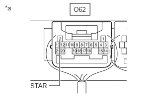
| *a | Component with harness connected
(Certification ECU (Smart Key ECU Assembly)) |
Measure the voltage according to the value(s) in the table below.
- Standard Voltage:
Tester Connection Condition Specified Condition O62-2 (STAR) - Body ground Engine switch pressed and held with brake pedal depressed (starter on) → Approximately 1 second after engine switch released (starter off) 6 V or higher* → 1.0 V or less
- HINT:
-
*: While the engine is cranking, the battery voltage may drop to approximately 6 V.
- Result:
Proceed to OK NG
OK
NG
Disconnect the O62 certification ECU (smart key ECU assembly) connector.
Disconnect the C62 park/neutral position switch assembly connector.
Measure the resistance according to the value(s) in the table below.
- Standard Resistance:
Tester Connection Condition Specified Condition O62-2 (STAR) - C62-4 (B) Always Below 1 Ω O62-2 (STAR) or C62-4 (B) - Other terminals and body ground Always 10 kΩ or higher
- Result:
Proceed to OK NG
OK
NG
Install the ST relay to the No. 1 engine room relay block and No. 1 junction block assembly.
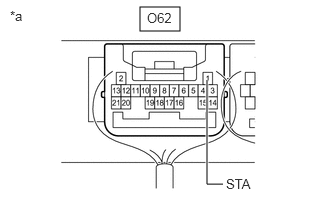
| *a | Component with harness connected
(Certification ECU (Smart Key ECU Assembly)) |
Measure the voltage according to the value(s) in the table below.
- Standard Voltage:
Tester Connection Condition Specified Condition O62-1 (STA) - Body ground Engine switch pressed and held with brake pedal depressed (starter on) → Approximately 1 second after engine switch released (starter off) 6 V or higher* → 1.0 V or less
- HINT:
-
*: While the engine is cranking, the battery voltage may drop to approximately 6 V.
- Result:
Proceed to OK NG
OK
NG
Disconnect the O62 certification ECU (smart key ECU assembly) connector.
Measure the resistance according to the value(s) in the table below.
- Standard Resistance:
Tester Connection Condition Specified Condition O62-1 (STA) - 1 (ST relay) Always Below 1 Ω O62-1 (STA) or 1 (ST relay) - Other terminals and body ground Always 10 kΩ or higher
- Result:
Proceed to OK NG
OK
NG
Measure the resistance according to the value(s) in the table below.
- Standard Resistance:
Tester Connection Condition Specified Condition C62-9 (L) - 1 (ST relay) Always Below 1 Ω C62-9 (L) or 1 (ST relay) - Other terminals and body ground Always 10 kΩ or higher
- Result:
Proceed to OK NG
OK
NG