MIRROR (INT) DIGITAL REAR-VIEW MIRROR SYSTEM The Camera Malfunction Indicator Displays and the Screen is Darkened
DESCRIPTION
The image signals sent from the inner mirror camera assembly are input to the inner rear view mirror assembly via the vehicle wire harness and then displayed on the screen.
WIRING DIAGRAM
except Double Swing Out Type
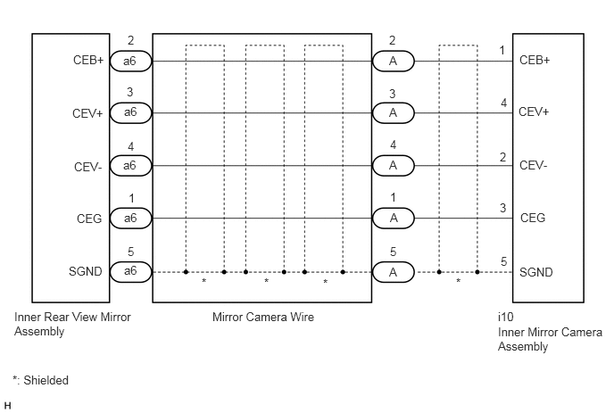
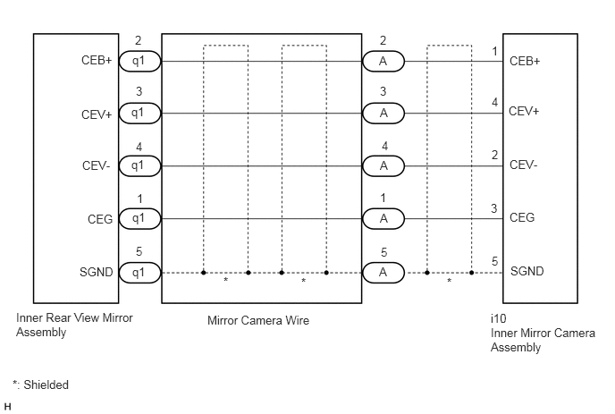
for Double Swing Out Type
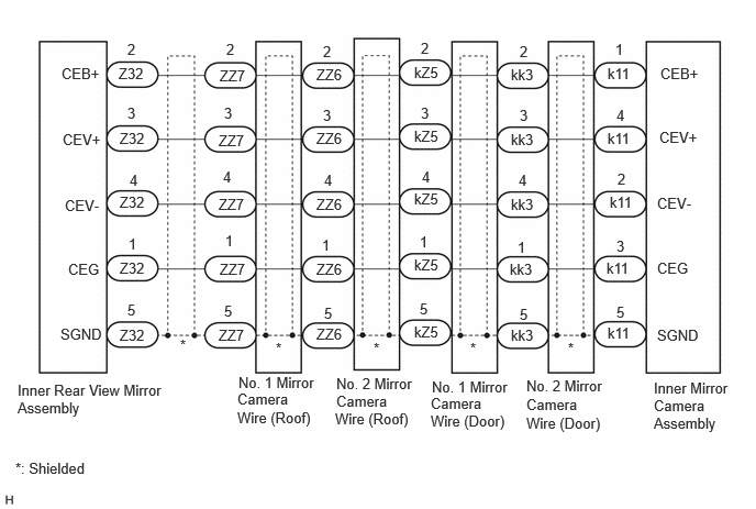
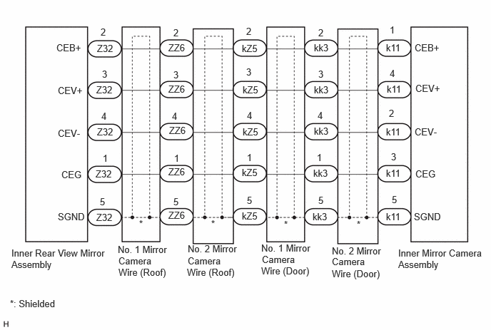
PROCEDURE
Check the vehicle type.
- Result:
Result Proceed to except Double Swing Out Type A for Double Swing Out Type B
A
B
Disconnect the a6*1 or q1*2 inner rear view mirror assembly connector.
*1: for Standard Roof
*2: for High Roof
Disconnect the i10 inner mirror camera assembly connector.
Measure the resistance according to the value(s) in the table below.
- Standard Resistance:
for Standard Roof Tester Connection Condition Specified Condition a6-1 (CEG) - i10-3 (CEG) Always Below 1 Ω a6-2 (CEB+) - i10-1 (CEB+) Always Below 1 Ω a6-3 (CEV+) - i10-4 (CEV+) Always Below 1 Ω a6-4 (CEV-) - i10-2 (CEV-) Always Below 1 Ω a6-5 (SGND) - i10-5 (SGND) Always Below 1 Ω a6-1 (CEG) or i10-3 (CEG) - Body ground Always 10 kΩ or higher a6-2 (CEB+) or i10-1 (CEB+) - Body ground Always 10 kΩ or higher a6-3 (CEV+) or i10-4 (CEV+) - Body ground Always 10 kΩ or higher a6-4 (CEV-) or i10-2 (CEV-) - Body ground Always 10 kΩ or higher a6-5 (SGND) or i10-5 (SGND) - Body ground Always 10 kΩ or higher
| Tester Connection | Condition | Specified Condition |
|---|---|---|
| q1-1 (CEG) - i10-3 (CEG) | Always | Below 1 Ω |
| q1-2 (CEB+) - i10-1 (CEB+) | Always | Below 1 Ω |
| q1-3 (CEV+) - i10-4 (CEV+) | Always | Below 1 Ω |
| q1-4 (CEV-) - i10-2 (CEV-) | Always | Below 1 Ω |
| q1-5 (SGND) - i10-5 (SGND) | Always | Below 1 Ω |
| q1-1 (CEG) or i10-3 (CEG) - Body ground | Always | 10 kΩ or higher |
| q1-2 (CEB+) or i10-1 (CEB+) - Body ground | Always | 10 kΩ or higher |
| q1-3 (CEV+) or i10-4 (CEV+) - Body ground | Always | 10 kΩ or higher |
| q1-4 (CEV-) or i10-2 (CEV-) - Body ground | Always | 10 kΩ or higher |
| q1-5 (SGND) or i10-5 (SGND) - Body ground | Always | 10 kΩ or higher |
- Result:
Proceed to OK NG
OK
NG
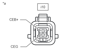
| *a | Front view of wire harness connector
(to Inner Mirror Camera Assembly) |
Disconnect the inner mirror camera assembly connector.
Measure the voltage according to the value(s) in the table below.
- Standard Voltage:
Tester Connection Switch Condition Specified Condition i10-1 (CEB+) - i10-3 (CEG) Ignition switch ON 5.5 V or higher
- Result:
Proceed to OK NG
OK
NG
Temporarily replace the inner mirror camera assembly with a new or normally functioning one.
Check that the digital rear-view mirror system is operating normally.
- OK:
The digital rear-view mirror system is operating normally.
- Result:
Proceed to OK NG
OK
NG
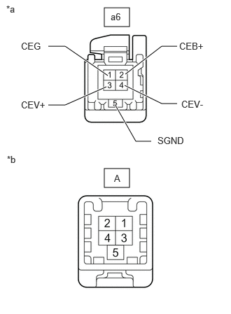
| *a | Front view of wire harness connector
(to Inner Rear View Mirror Assembly) |
| *b | Front view of wire harness connector
(to Mirror Camera Wire) |
for Standard Roof:
Disconnect the a6 inner rear view mirror assembly connector.
Disconnect the A mirror camera wire connector.
Measure the resistance according to the value(s) in the table below.
- Standard Resistance:
Tester Connection Condition Specified Condition a6-1 (CEG) - A-1 Always Below 1 Ω a6-2 (CEB+) - A-2 Always Below 1 Ω a6-3 (CEV+) - A-3 Always Below 1 Ω a6-4 (CEV-) - A-4 Always Below 1 Ω a6-5 (SGND) - A-5 Always Below 1 Ω a6-1 (CEG) or A-1 - Body ground Always 10 kΩ or higher a6-2 (CEB+) or A-2 - Body ground Always 10 kΩ or higher a6-3 (CEV+) or A-3 - Body ground Always 10 kΩ or higher a6-4 (CEV-) or A-4 - Body ground Always 10 kΩ or higher a6-5 (SGND) or A-5 - Body ground Always 10 kΩ or higher
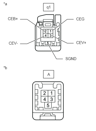
| *a | Front view of wire harness connector
(to Inner Rear View Mirror Assembly) |
| *b | Front view of wire harness connector
(to Mirror Camera Wire) |
for High Roof:
Disconnect the q1 inner rear view mirror assembly connector.
Disconnect the A mirror camera wire connector.
Measure the resistance according to the value(s) in the table below.
- Standard Resistance:
Tester Connection Condition Specified Condition q1-1 (CEG) - A-1 Always Below 1 Ω q1-2 (CEB+) - A-2 Always Below 1 Ω q1-3 (CEV+) - A-3 Always Below 1 Ω q1-4 (CEV-) - A-4 Always Below 1 Ω q1-5 (SGND) - A-5 Always Below 1 Ω q1-1 (CEG) or A-1 - Body ground Always 10 kΩ or higher q1-2 (CEB+) or A-2 - Body ground Always 10 kΩ or higher q1-3 (CEV+) or A-3 - Body ground Always 10 kΩ or higher q1-4 (CEV-) or A-4 - Body ground Always 10 kΩ or higher q1-5 (SGND) or A-5 - Body ground Always 10 kΩ or higher
- Result:
Proceed to OK NG
OK
NG
for Semi-trim:
for Full-trim:
Check the vehicle type.
- Result:
Result Proceed to for Standard Roof A for High Roof B
A
B
Disconnect the Z32 or inner rear view mirror assembly connector.
Disconnect the k11 inner mirror camera assembly connector.
Measure the resistance according to the value(s) in the table below.
- Standard Resistance:
Tester Connection Condition Specified Condition Z32-1 (CEG) - k11-3 (CEG) Always Below 1 Ω Z32-2 (CEB+) - k11-1 (CEB+) Always Below 1 Ω Z32-3 (CEV+) - k11-4 (CEV+) Always Below 1 Ω Z32-4 (CEV-) - k11-2 (CEV-) Always Below 1 Ω Z32-5 (SGND) - k11-5 (SGND) Always Below 1 Ω Z32-1 (CEG) or k11-3 (CEG) - Body ground Always 10 kΩ or higher Z32-2 (CEB+) or k11-1 (CEB+) - Body ground Always 10 kΩ or higher Z32-3 (CEV+) or k11-4 (CEV+) - Body ground Always 10 kΩ or higher Z32-4 (CEV-) or k11-2 (CEV-) - Body ground Always 10 kΩ or higher Z32-5 (SGND) or k11-5 (SGND) - Body ground Always 10 kΩ or higher
- Result:
Proceed to OK NG
OK
NG
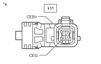
| *a | Front view of wire harness connector
(to Inner Mirror Camera Assembly) |
Disconnect the inner mirror camera assembly connector.
Measure the voltage according to the value(s) in the table below.
- Standard Voltage:
Tester Connection Switch Condition Specified Condition k11-1 (CEB+) - k11-3 (CEG) Ignition switch ON 5.5 V or higher
- Result:
Proceed to OK NG
OK
NG
Temporarily replace the inner mirror camera assembly with a new or normally functioning one.
Check that the digital rear-view mirror system is operating normally.
- OK:
The digital rear-view mirror system is operating normally.
- Result:
Proceed to OK NG
OK
NG
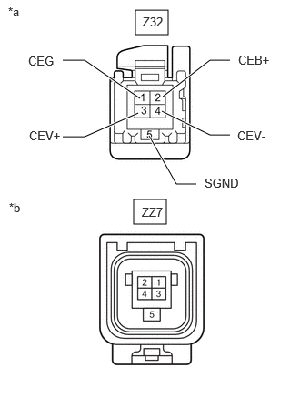
| *a | Front view of wire harness connector
(to Inner Rear View Mirror Assembly) |
| *b | Front view of wire harness connector
(No. 1 Mirror Camera Wire (Roof)) |
Disconnect the Z32 inner rear view mirror assembly connector.
Disconnect the ZZ7 No. 1 mirror camera wire (roof) connector.
Measure the resistance according to the value(s) in the table below.
- Standard Resistance:
Tester Connection Condition Specified Condition Z32-1 (CEG) - ZZ7-1 Always Below 1 Ω Z32-2 (CEB+) - ZZ7-2 Always Below 1 Ω Z32-3 (CEV+) - ZZ7-3 Always Below 1 Ω Z32-4 (CEV-) - ZZ7-4 Always Below 1 Ω Z32-5 (SGND) - ZZ7-5 Always Below 1 Ω Z32-1 (CEG) or ZZ7-1 - Body ground Always 10 kΩ or higher Z32-2 (CEB+) or ZZ7-2 - Body ground Always 10 kΩ or higher Z32-3 (CEV+) or ZZ7-3 - Body ground Always 10 kΩ or higher Z32-4 (CEV-) or ZZ7-4 - Body ground Always 10 kΩ or higher Z32-5 (SGND) or ZZ7-5 - Body ground Always 10 kΩ or higher
- Result:
Proceed to OK NG
OK
NG
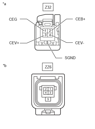
| *a | Front view of wire harness connector
(to Inner Rear View Mirror Assembly) |
| *b | Front view of wire harness connector
(No. 2 Mirror Camera Wire (Roof)) |
Disconnect the Z32 inner rear view mirror assembly connector.
Disconnect the ZZ6 No. 2 mirror camera wire (roof) connector.
Measure the resistance according to the value(s) in the table below.
- Standard Resistance:
Tester Connection Condition Specified Condition Z32-1 (CEG) - ZZ6-1 Always Below 1 Ω Z32-2 (CEB+) - ZZ6-2 Always Below 1 Ω Z32-3 (CEV+) - ZZ6-3 Always Below 1 Ω Z32-4 (CEV-) - ZZ6-4 Always Below 1 Ω Z32-5 (SGND) - ZZ6-5 Always Below 1 Ω Z32-1 (CEG) or ZZ6-1 - Body ground Always 10 kΩ or higher Z32-2 (CEB+) or ZZ6-2 - Body ground Always 10 kΩ or higher Z32-3 (CEV+) or ZZ6-3 - Body ground Always 10 kΩ or higher Z32-4 (CEV-) or ZZ6-4 - Body ground Always 10 kΩ or higher Z32-5 (SGND) or ZZ6-5 - Body ground Always 10 kΩ or higher
- Result:
Proceed to OK NG
OK
NG
for Semi-trim:
for Full-trim:
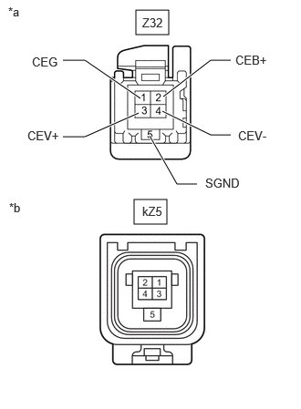
| *a | Front view of wire harness connector
(to Inner Rear View Mirror Assembly) |
| *b | Front view of wire harness connector
(to No. 1 Mirror Camera Wire (Door)) |
Disconnect the Z32 inner rear view mirror assembly connector.
Disconnect the kZ5 No. 1 mirror camera wire (door) connector.
Measure the resistance according to the value(s) in the table below.
| Tester Connection | Condition | Specified Condition |
|---|---|---|
| Z32-1 (CEG) - kZ5-1 | Always | Below 1 Ω |
| Z32-2 (CEB+) - kZ5-2 | Always | Below 1 Ω |
| Z32-3 (CEV+) - kZ5-3 | Always | Below 1 Ω |
| Z32-4 (CEV-) - kZ5-4 | Always | Below 1 Ω |
| Z32-5 (SGND) - kZ5-5 | Always | Below 1 Ω |
| Z32-1 (CEG) or kZ5-1 - Body ground | Always | 10 kΩ or higher |
| Z32-2 (CEB+) or kZ5-2 - Body ground | Always | 10 kΩ or higher |
| Z32-3 (CEV+) or kZ5-3 - Body ground | Always | 10 kΩ or higher |
| Z32-4 (CEV-) or kZ5-4 - Body ground | Always | 10 kΩ or higher |
| Z32-5 (SGND) or kZ5-5 - Body ground | Always | 10 kΩ or higher |
- Result:
Proceed to OK NG
OK
NG
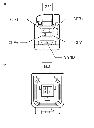
| *a | Front view of wire harness connector
(to Inner Rear View Mirror Assembly) |
| *b | Front view of wire harness connector
(to No. 2 Mirror Camera Wire (Door)) |
Disconnect the Z32 inner rear view mirror assembly connector.
Disconnect the kk3 No. 2 mirror camera wire (door) connector.
Measure the resistance according to the value(s) in the table below.
| Tester Connection | Condition | Specified Condition |
|---|---|---|
| Z32-1 (CEG) - kk3-1 | Always | Below 1 Ω |
| Z32-2 (CEB+) - kk3-2 | Always | Below 1 Ω |
| Z32-3 (CEV+) - kk3-3 | Always | Below 1 Ω |
| Z32-4 (CEV-) - kk3-4 | Always | Below 1 Ω |
| Z32-5 (SGND) - kk3-5 | Always | Below 1 Ω |
| Z32-1 (CEG) or kk3-1 - Body ground | Always | 10 kΩ or higher |
| Z32-2 (CEB+) or kk3-2 - Body ground | Always | 10 kΩ or higher |
| Z32-3 (CEV+) or kk3-3 - Body ground | Always | 10 kΩ or higher |
| Z32-4 (CEV-) or kk3-4 - Body ground | Always | 10 kΩ or higher |
| Z32-5 (SGND) or kk3-5 - Body ground | Always | 10 kΩ or higher |
- Result:
Proceed to OK NG
OK
NG
Disconnect the Z32 inner rear view mirror assembly connector.
Disconnect the k11 inner mirror camera assembly connector.
Measure the resistance according to the value(s) in the table below.
- Standard Resistance:
Tester Connection Condition Specified Condition Z32-1 (CEG) - k11-3 (CEG) Always Below 1 Ω Z32-2 (CEB+) - k11-1 (CEB+) Always Below 1 Ω Z32-3 (CEV+) - k11-4 (CEV+) Always Below 1 Ω Z32-4 (CEV-) - k11-2 (CEV-) Always Below 1 Ω Z32-5 (SGND) - k11-5 (SGND) Always Below 1 Ω Z32-1 (CEG) or k11-3 (CEG) - Body ground Always 10 kΩ or higher Z32-2 (CEB+) or k11-1 (CEB+) - Body ground Always 10 kΩ or higher Z32-3 (CEV+) or k11-4 (CEV+) - Body ground Always 10 kΩ or higher Z32-4 (CEV-) or k11-2 (CEV-) - Body ground Always 10 kΩ or higher Z32-5 (SGND) or k11-5 (SGND) - Body ground Always 10 kΩ or higher
- Result:
Proceed to OK NG
OK
NG
| *a | Front view of wire harness connector
(to Inner Mirror Camera Assembly) |
Disconnect the inner mirror camera assembly connector.
Measure the voltage according to the value(s) in the table below.
- Standard Voltage:
Tester Connection Switch Condition Specified Condition k11-1 (CEB+) - k11-3 (CEG) Ignition switch ON 5.5 V or higher
- Result:
Proceed to OK NG
OK
NG
Temporarily replace the inner mirror camera assembly with a new or normally functioning one.
Check that the digital rear-view mirror system is operating normally.
- OK:
The digital rear-view mirror system is operating normally.
- Result:
Proceed to OK NG
OK
NG
| *a | Front view of wire harness connector
(to Inner Rear View Mirror Assembly) |
| *b | Front view of wire harness connector
(No. 2 Mirror Camera Wire (Roof)) |
Disconnect the Z32 inner rear view mirror assembly connector.
Disconnect the ZZ6 No. 2 mirror camera wire (roof) connector.
Measure the resistance according to the value(s) in the table below.
- Standard Resistance:
Tester Connection Condition Specified Condition Z32-1 (CEG) - ZZ6-1 Always Below 1 Ω Z32-2 (CEB+) - ZZ6-2 Always Below 1 Ω Z32-3 (CEV+) - ZZ6-3 Always Below 1 Ω Z32-4 (CEV-) - ZZ6-4 Always Below 1 Ω Z32-5 (SGND) - ZZ6-5 Always Below 1 Ω Z32-1 (CEG) or ZZ6-1 - Body ground Always 10 kΩ or higher Z32-2 (CEB+) or ZZ6-2 - Body ground Always 10 kΩ or higher Z32-3 (CEV+) or ZZ6-3 - Body ground Always 10 kΩ or higher Z32-4 (CEV-) or ZZ6-4 - Body ground Always 10 kΩ or higher Z32-5 (SGND) or ZZ6-5 - Body ground Always 10 kΩ or higher
- Result:
Proceed to OK NG
OK
NG
for Semi-trim:
for Full-trim:
| *a | Front view of wire harness connector
(to Inner Rear View Mirror Assembly) |
| *b | Front view of wire harness connector
(to No. 1 Mirror Camera Wire (Door)) |
Disconnect the Z32 inner rear view mirror assembly connector.
Disconnect the kZ5 No. 1 mirror camera wire (door) connector.
Measure the resistance according to the value(s) in the table below.
| Tester Connection | Condition | Specified Condition |
|---|---|---|
| Z32-1 (CEG) - kZ5-1 | Always | Below 1 Ω |
| Z32-2 (CEB+) - kZ5-2 | Always | Below 1 Ω |
| Z32-3 (CEV+) - kZ5-3 | Always | Below 1 Ω |
| Z32-4 (CEV-) - kZ5-4 | Always | Below 1 Ω |
| Z32-5 (SGND) - kZ5-5 | Always | Below 1 Ω |
| Z32-1 (CEG) or kZ5-1 - Body ground | Always | 10 kΩ or higher |
| Z32-2 (CEB+) or kZ5-2 - Body ground | Always | 10 kΩ or higher |
| Z32-3 (CEV+) or kZ5-3 - Body ground | Always | 10 kΩ or higher |
| Z32-4 (CEV-) or kZ5-4 - Body ground | Always | 10 kΩ or higher |
| Z32-5 (SGND) or kZ5-5 - Body ground | Always | 10 kΩ or higher |
- Result:
Proceed to OK NG
OK
NG
| *a | Front view of wire harness connector
(to Inner Rear View Mirror Assembly) |
| *b | Front view of wire harness connector
(to No. 2 Mirror Camera Wire (Door)) |
Disconnect the Z32 inner rear view mirror assembly connector.
Disconnect the kk3 No. 2 mirror camera wire (door) connector.
Measure the resistance according to the value(s) in the table below.
| Tester Connection | Condition | Specified Condition |
|---|---|---|
| Z32-1 (CEG) - kk3-1 | Always | Below 1 Ω |
| Z32-2 (CEB+) - kk3-2 | Always | Below 1 Ω |
| Z32-3 (CEV+) - kk3-3 | Always | Below 1 Ω |
| Z32-4 (CEV-) - kk3-4 | Always | Below 1 Ω |
| Z32-5 (SGND) - kk3-5 | Always | Below 1 Ω |
| Z32-1 (CEG) or kk3-1 - Body ground | Always | 10 kΩ or higher |
| Z32-2 (CEB+) or kk3-2 - Body ground | Always | 10 kΩ or higher |
| Z32-3 (CEV+) or kk3-3 - Body ground | Always | 10 kΩ or higher |
| Z32-4 (CEV-) or kk3-4 - Body ground | Always | 10 kΩ or higher |
| Z32-5 (SGND) or kk3-5 - Body ground | Always | 10 kΩ or higher |
- Result:
Proceed to OK NG
OK
NG