STEERING COLUMN STEERING COLUMN ASSEMBLY INSTALLATION
PROCEDURE

 1.ALIGN FRONT WHEELS FACING STRAIGHT AHEAD
45250
2.INSTALL STEERING COLUMN ASSEMBLY
- NOTICE:
-
Make sure that the wire harness is not interfering with the steering column assembly.
Install the steering column assembly with the bolt and 2 nuts.
- Torque:
- 36 N*m (367 kgf*cm, 27 ft.*lbf)
- NOTICE:
- ·
After the column is installed, check the tilt and telescopic operation.
·If a large amount of force is required to operate the tilt mechanism or abnormal noise occurs, loosen the nuts and move the bracket forward or backward until the tilt operation works smoothly.
Tighten the nuts and check the tilt operation again.
Connect each connector and engage each wire harness clamp to the steering column assembly.
3.INSTALL INTERMEDIATE SHAFT ASSEMBLY
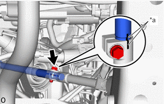
| *a | Matchmark |
Align the matchmarks on the No. 1 steering intermediate shaft assembly and No. 2 steering intermediate shaft assembly.
- HINT:
-
Perform this procedure only when replacement of the No. 1 steering intermediate shaft assembly and No. 2 steering intermediate shaft assembly is necessary.
Install the No. 1 steering intermediate shaft assembly and No. 2 steering intermediate shaft assembly.
- HINT:
-
Perform this procedure only when replacement of the No. 1 steering intermediate shaft assembly and No. 2 steering intermediate shaft assembly is necessary.
Install the bolt.
- Torque:
- 35 N*m (357 kgf*cm, 26 ft.*lbf)
- HINT:
-
Perform this procedure only when replacement of the No. 1 steering intermediate shaft assembly and No. 2 steering intermediate shaft assembly is necessary.
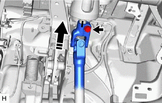
| *a | Matchmark |
Align the matchmarks on the steering intermediate shaft assembly and steering column assembly.
Install the steering intermediate shaft assembly to the steering column assembly.
Install the bolt.
- Torque:
- 35 N*m (357 kgf*cm, 26 ft.*lbf)
Connect the steering intermediate shaft assembly to the rack and pinion power steering gear assembly.
4.INSTALL FRONT WHEEL LH (for LHD)
5.INSTALL FRONT WHEEL RH (for RHD)
73900
6.INSTALL LOWER NO. 1 INSTRUMENT PANEL AIRBAG ASSEMBLY (w/ Driver Side Knee Airbag)
55313
7.INSTALL LOWER INSTRUMENT PANEL LH (w/o Driver Side Knee Airbag)
55445B
8.INSTALL INSTRUMENT PANEL FINISH PLATE (w/o Driver Side Knee Airbag)
55433B
9.INSTALL LOWER NO. 2 INSTRUMENT PANEL FINISH PANEL
55432D
10.INSTALL LOWER NO. 1 INSTRUMENT PANEL FINISH PANEL
55641
11.INSTALL NO. 1 INSTRUMENT PANEL UNDER COVER
55318C
12.INSTALL INSTRUMENT SIDE PANEL LH
55011A
13.INSTALL NO. 1 INSTRUMENT PANEL GARNISH SUB-ASSEMBLY
55631A
14.INSTALL NO. 1 INSTRUMENT PANEL UNDER TRAY STOPPER
62112
15.INSTALL COWL SIDE TRIM BOARD LH
67914B
16.INSTALL FRONT DOOR SCUFF PLATE LH
67912A
17.INSTALL FRONT DOOR OUTSIDE SCUFF PLATE LH
18.INSTALL TURN SIGNAL SWITCH ASSEMBLY WITH SPIRAL CABLE SUB-ASSEMBLY
- NOTICE:
- ·
Do not replace the spiral cable with sensor sub-assembly with the battery connected and the ignition switch ON.
·Do not rotate the spiral cable with sensor sub-assembly without the steering wheel assembly installed, with the battery connected and the ignition switch ON.
·Ensure that the steering wheel assembly is installed and aligned straight when inspecting the steering sensor.
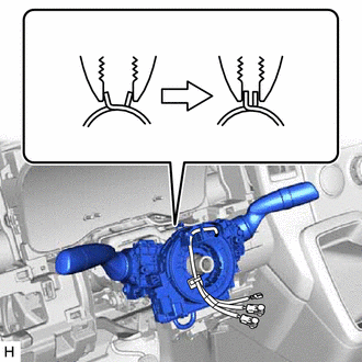
Using pliers, support the band clamp while loosened and set the turn signal switch assembly with spiral cable sub-assembly.
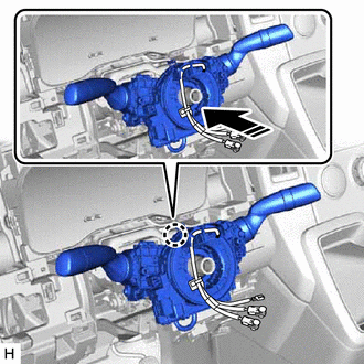

|
Install in this Direction |
Attach the claw to install the turn signal switch assembly with spiral cable sub-assembly to the steering column assembly as shown in the illustration.
Tighten the band clamp.
Connect each connector to the turn signal switch assembly with spiral cable sub-assembly.
45286B
19.INSTALL UPPER STEERING COLUMN COVER
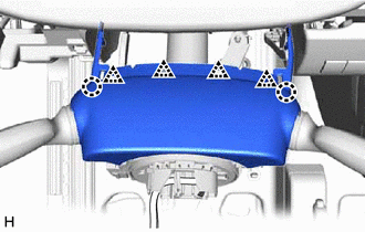
Attach the 2 claws and 4 clips to connect the upper steering column cover.
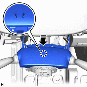
|
|
Install in this Direction |
Attach the claw to install the upper steering column cover.
45024
20.INSTALL LOWER STEERING COLUMN COVER SUB-ASSEMBLY
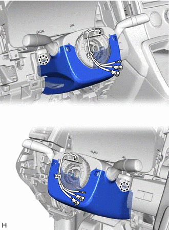
Attach the 2 claws to install the lower steering column cover sub-assembly.
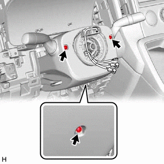
Install the 3 screws.
21.INSTALL STEERING WHEEL ASSEMBLY
22.ALIGN FRONT WHEELS FACING STRAIGHT AHEAD
84306
23.INSPECT AND ADJUST SPIRAL CABLE WITH SENSOR SUB-ASSEMBLY
24.CHECK STEERING WHEEL CENTER POINT
45130
25.INSTALL HORN BUTTON ASSEMBLY
26.CONNECT CABLE TO NEGATIVE BATTERY TERMINAL
27. INITIALIZATION AFTER RECONNECTING BATTERY TERMINAL (w/ Airbag System)
- HINT:
-
When disconnecting and reconnecting the battery, there is an automatic learning function that completes learning when the respective system is used.
28.PERFORM DIAGNOSTIC SYSTEM CHECK
29.CHECK SRS WARNING LIGHT