HEATING / AIR CONDITIONING FRONT EVAPORATOR TEMPERATURE SENSOR INSTALLATION
PROCEDURE

 88625
1.INSTALL NO. 1 COOLER THERMISTOR (FRONT EVAPORATOR TEMPERATURE SENSOR) (for LHD)
88625
1.INSTALL NO. 1 COOLER THERMISTOR (FRONT EVAPORATOR TEMPERATURE SENSOR) (for LHD)
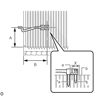
| *a | Fixed Part |
| *b | Sensor Part |
Install the No. 1 cooler thermistor (front evaporator temperature sensor) as shown in the illustration.
- NOTICE:
- ·
Be sure to insert the No. 1 cooler thermistor (front evaporator temperature sensor) only once because reinserting it into the same position will not allow it to be firmly secured.
·When reusing the No. 1 cooler evaporator sub-assembly, insert the sensor part of the No. 1 cooler thermistor (front evaporator temperature sensor) one row from the row that had been used previously (X in the illustration).
·After inserting the No. 1 cooler thermistor (front evaporator temperature sensor), do not apply excessive force to the wire.
·Directly insert the No. 1 cooler thermistor (front evaporator temperature sensor), until the edge of the plastic case "a" comes into contact with the No. 1 cooler evaporator sub-assembly "b".
- Installation Position:
Position Measurement A 45 to 55 mm (1.77 to 2.17 in.) B 61.1 mm (2.41 in.) (9 Fins)
88625
2.INSTALL NO. 1 COOLER THERMISTOR (FRONT EVAPORATOR TEMPERATURE SENSOR) (for RHD)

| *A | w/o Stop and Start System |
| *B | w/ Stop and Start System |
| *a | Fixed Part |
| *b | Sensor Part |
Install the No. 1 cooler thermistor (front evaporator temperature sensor) as shown in the illustration.
- NOTICE:
- ·
Be sure to insert the No. 1 cooler thermistor (front evaporator temperature sensor) only once because reinserting it into the same position will not allow it to be firmly secured.
·When reusing the No. 1 cooler evaporator sub-assembly, insert the sensor part of the No. 1 cooler thermistor (front evaporator temperature sensor) one row from the row that had been used previously (X in the illustration).
·After inserting the No. 1 cooler thermistor (front evaporator temperature sensor), do not apply excessive force to the wire.
·Directly insert the No. 1 cooler thermistor (front evaporator temperature sensor), until the edge of the plastic case "a" comes into contact with the No. 1 cooler evaporator sub-assembly "b".
- Installation Position:
Position Measurement A 45 to 55 mm (1.77 to 2.17 in.) B 61.1 mm (2.41 in.) (9 Fins) C 23 to 27 mm (0.91 to 1.06 in.) D 54.4 mm (2.14 in.)(8 Fins)
88501
3.INSTALL NO. 1 COOLER EVAPORATOR SUB-ASSEMBLY
88515
4.INSTALL COOLER EXPANSION VALVE
88899L
5.INSTALL COOLING UNIT PARTS
88482
6.INSTALL COOLER CAP (w/o Cooler System)
87107A
7.INSTALL HEATER RADIATOR UNIT SUB-ASSEMBLY (w/ Heater System)
87124B
8.INSTALL HEATER CLAMP (w/ Heater System)
87128
9.INSTALL HEATER GROMMET
82210K
10.INSTALL AIR CONDITIONING HARNESS ASSEMBLY (for Automatic Air Conditioning System)
87130D
11.INSTALL BLOWER ASSEMBLY
12.CONNECT CABLE TO NEGATIVE BATTERY TERMINAL
13. INITIALIZATION AFTER RECONNECTING BATTERY TERMINAL
- HINT:
-
When disconnecting and reconnecting the battery, there is an automatic learning function that completes learning when the respective system is used.
14.PERFORM DIAGNOSTIC SYSTEM CHECK
15.CHECK SRS WARNING LIGHT