BRAKE CONTROL / DYNAMIC CONTROL SYSTEMS ELECTRONICALLY CONTROLLED BRAKE SYSTEM(w/ VSC OFF Switch) C004013 Brake Pedal Switch "A" Circuit Open
DESCRIPTION
The brake pedal load sensing switch turns on when the brake pedal is depressed with a force exceeding a predetermined level.
The skid control ECU uses this circuit to detect if the brake pedal is depressed or not.
| DTC No. | Detection Item | DTC Detection Condition | Trouble Area |
|---|---|---|---|
| C004013 | Brake Pedal Switch "A" Circuit Open | An open or short in the brake pedal load sensing switch circuit continues for 0.5 seconds or more. | ·
Brake pedal load sensing switch (Brake pedal support assembly) ·
Brake pedal load sensing switch circuit ·
Skid control ECU (Brake actuator assembly) |
| Vehicle Condition | |||
|---|---|---|---|
| Pattern 1 | Pattern 2 | ||
| Diagnosis Condition | - | - | - |
| Malfunction Status | An open in the brake pedal load sensing switch circuit continues. | ○ | - |
| A short in the brake pedal load sensing switch circuit continues. | - | ○ | |
| Detection Time | 0.5 seconds or more | 0.5 seconds or more | |
| Number of Trips | 1 trip | 1 trip | |
WIRING DIAGRAM
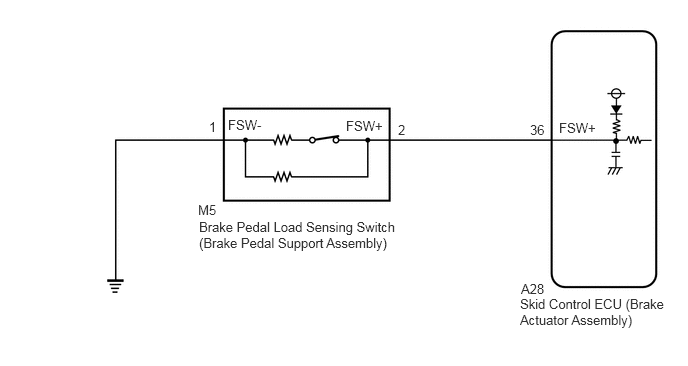
CAUTION / NOTICE / HINT
- HINT:
-
When P057111, P057112, and/or P057113 is output together with C004013, inspect and repair the trouble areas indicated by P057111, P057112, and/or P057113 first: (Click hereBrake>BRAKE CONTROL / DYNAMIC CONTROL SYSTEMS>ELECTRONICALLY CONTROLLED BRAKE SYSTEM (w/ VSC OFF Switch)>P057111201906,202107,_54,_078667,_0385049,RM100000001IQ9S,P057111202107,999999,_54,_078667,_0385049,RM100000001XSNN,P057111), (Click hereBrake>BRAKE CONTROL / DYNAMIC CONTROL SYSTEMS>ELECTRONICALLY CONTROLLED BRAKE SYSTEM (w/ VSC OFF Switch)>P057112201906,202107,_54,_078667,_0385049,RM100000001IQ9U,P057112202107,999999,_54,_078667,_0385049,RM100000001XVV6,P057112), and/or (Click hereBrake>BRAKE CONTROL / DYNAMIC CONTROL SYSTEMS>ELECTRONICALLY CONTROLLED BRAKE SYSTEM (w/ VSC OFF Switch)>P057113201906,999999,_54,_078667,_0385049,RM100000001IQ9Z,P057113).
PROCEDURE
Connect the GTS to the DLC3.
Turn the ignition switch to ON.
Select the Data List using the GTS.
- Chassis > Brake > Data List
-
Tester Display Measurement Item Range Normal Condition Diagnostic Note Brake Pedal Load Sensing SW Brake pedal load sensing switch (brake pedal support assembly) OFF / ON OFF: Brake pedal load sensing switch (brake pedal support assembly) OFF
ON: Brake pedal load sensing switch (brake pedal support assembly) ON-
- Chassis > Brake > Data List
-
Tester Display Brake Pedal Load Sensing SW - 50003 435 61
Check that the brake pedal load sensing switch display observed on the GTS changes according to brake pedal operation.
- OK:
The GTS displays ON or OFF according to brake pedal operation.
- Result:
Proceed to OK NG
OK
NG
Connect the GTS to the DLC3.
Turn the ignition switch to ON.
Operate the GTS to clear the codes. Enter the following menus: Chassis / Brake / Trouble Codes.
- Chassis > Brake > Clear DTCs
- 50002 435
Press the DTC clear button.
- Result:
Proceed to NEXT
NEXT
Connect the GTS to the DLC3.
Start the engine.
Perform a road test under the same malfunction conditions recreated based on the Freeze Frame Data or customer problem analysis.
Read the DTCs following the prompts on the GTS. Enter the following menus: Chassis / Brake / Trouble Codes.
- Chassis > Brake > Trouble Codes
- 50001 435
Check if the same DTC is output.
- Result:
Result Proceed to C004013 is not output A C004013 is output B
A
B
Inspect the brake pedal load sensing switch (brake pedal support assembly).
for LHD: Click hereBrake>BRAKE SYSTEM (OTHER)>BRAKE PEDAL (for LHD)>ON-VEHICLE INSPECTION201906,999999,_54,_078668,_0381534,RM100000001IPHA,
for RHD: Click hereBrake>BRAKE SYSTEM (OTHER)>BRAKE PEDAL (for RHD)>ON-VEHICLE INSPECTION201906,999999,_54,_078668,_0381535,RM100000001IPI8,
- OK:
The brake pedal load sensing switch (brake pedal support assembly) is normal.
- Result:
Proceed to OK NG
OK
NG
for LHD: Click hereBrake>BRAKE SYSTEM (OTHER)>BRAKE PEDAL (for LHD)>REMOVAL201906,202310,_54,_078668,_0381534,RM100000001IPGV,202310,999999,_54,_078668,_0381534,RM100000002G2A7,
for RHD: Click hereBrake>BRAKE SYSTEM (OTHER)>BRAKE PEDAL (for RHD)>REMOVAL201906,202310,_54,_078668,_0381535,RM100000001IPI6,202310,999999,_54,_078668,_0381535,RM100000002G2AB,
Make sure that there is no looseness at the locking part and the connecting part of the connector.
Disconnect the A28 skid control ECU (brake actuator assembly) connector.
Measure the resistance according to the value(s) in the table below.
- Standard Resistance:
Tester Connection Condition Specified Condition A28-36 (FSW+) - M5-2 (FSW+) Always Below 1 Ω A28-36 (FSW+) - Body ground Always 10 kΩ or higher M5-2 (FSW+) - Body ground Always 10 kΩ or higher M5-1 (FSW-) - Body ground Always Below 1 Ω
- Result:
Proceed to OK NG
OK
NG