RM35X0E
_54
Brake
_078668
BRAKE SYSTEM (OTHER)
_0381534
BRAKE PEDAL(for LHD)
G
BRAKE SYSTEM (OTHER) BRAKE PEDAL(for LHD) ON-VEHICLE INSPECTION
PROCEDURE

 1.INSPECT BRAKE PEDAL LOAD SENSING SWITCH (w/ Brake pedal Load Sensing Switch)
a.
Make sure that there is no looseness in the locking part and the connection part of the connector.
b.
Disconnect the brake pedal load sensing switch (brake pedal support assembly) connector.
c.
Check both the connector case and the terminal for deformation and corrosion.
- OK:
No deformation or corrosion.
- NOTICE:
- ·
Do not remove the brake pedal load sensing switch from the brake pedal support assembly.
·When there is a malfunction in the brake pedal load sensing switch, replace the brake pedal support assembly.
d.
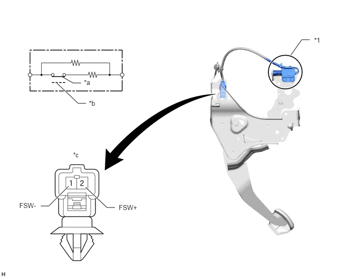
Measure the resistance according to the value(s) in the table below.
6.094,1.156 6.323,0.833
6.323,0.833 6.49,0.833
false
1.292,1.604 1.531,1.74
1.531,1.74 1.698,1.74
false
1.188,1.74 1.635,2.167
1.635,2.167 1.802,2.167
true
1.792,3.927 2.24,4.354
2.24,4.354 2.406,4.354
true
0.854,4.323 1.021,4.323
1.021,4.323 1.438,3.906
true
6.583,0.76 6.865,1
0.281,0.24
10
false
*1
2.49,4.271 3.094,4.604
0.604,0.333
10
false
FSW+
1.76,1.646 2.073,1.802
0.313,0.156
10
false
*a
1.865,2.083 2.177,2.24
0.313,0.156
10
false
*b
1.531,3.167 1.844,3.323
0.313,0.156
10
false
*c
0.406,4.229 1.01,4.563
0.604,0.333
10
false
FSW-
| *1 | Brake Pedal Load Sensing Switch | - | - |
| *a | Brake pedal released (ON) | *b | Brake pedal depressed (OFF) |
| *c | Component without harness connected
(Brake Pedal Load Sensing Switch) |
- | - |
- Standard Resistance:
Tester Connection Condition Specified Condition 1 (FSW-) - 2 (FSW+) Switch OFF
(Brake pedal depressed)950 to 1050 Ω Switch ON
(Brake pedal released)203 to 223 Ω