DOOR / HATCH REAR DOOR OPENING TRIM WEATHERSTRIP(for Wagon) INSTALLATION
CAUTION / NOTICE / HINT
- HINT:
- ·
Use the same procedure for RHD and LHD vehicles.
·The procedure listed below is for LHD vehicles.
·Use the same procedure for the RH and LH sides.
·Use the same procedure described for the RH side.
PROCEDURE

 67871E
1.INSTALL NO. 1 SLIDE DOOR WEATHERSTRIP RH
67871E
1.INSTALL NO. 1 SLIDE DOOR WEATHERSTRIP RH
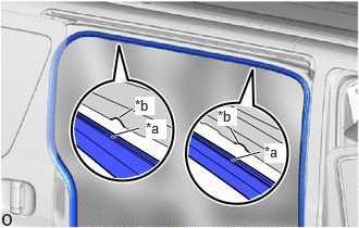
| *a | Paint Mark |
| *b | Cutout |
Install the No. 1 slide door weatherstrip RH.
Match the cutout on the front side of the top of the door opening with the paint mark of the No. 1 slide door weatherstrip RH.
Match the cutout on the rear side of the top of the door opening with the paint mark of the No. 1 slide door weatherstrip RH and install the No. 1 slide door weatherstrip RH to the top of the door opening.
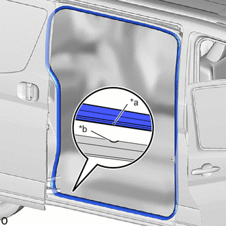
| *a | Connecting Portion |
| *b | Cutout |
Match the cutout on the bottom of the door opening with the connecting portion of the No. 1 slide door weatherstrip RH.
Install the No. 1 slide door weatherstrip RH on the rear side of the door opening.
Install the No. 1 slide door weatherstrip RH on the front and bottom sides of the door opening.
- NOTICE:
- ·
Always align the paint mark when installing the part. If the paint mark position is out of place, water leaks may occur.
·After the installation, check that the corners are properly installed.
- HINT:
-
To easily install the weatherstrip, first install the area with the paint mark as shown in the illustration. Then install the part toward the corners and push any excess length into the corners.
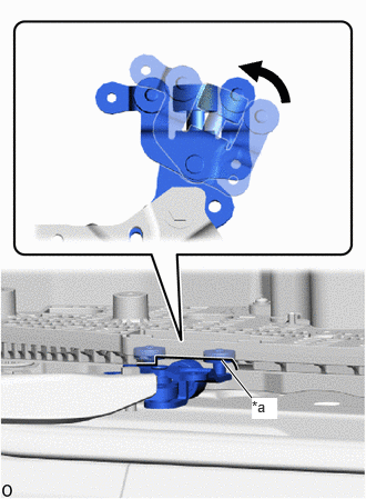
| *a | Cutout |
Rotate the roller part of the slide door lower roller arm sub-assembly RH counterclockwise to connect the slide door lower roller arm sub-assembly RH to the cutout of the slide door motor unit RH.
- NOTICE:
- ·
Support the lower portion of the slide door RH when connecting the slide door lower roller arm sub-assembly RH, as the slide door RH becomes unstable.
·Work with 2 or more persons when connecting the slide door RH in order to prevent deformation and damage.
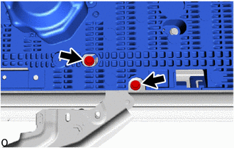
w/ Power Slide Door:
Move the slide door RH so that the 2 bolts are visible as shown in the illustration.
Install the lower slide door roller arm RH to the slide door motor unit RH with the 2 bolts.
- Torque:
- 7.8 N*m (80 kgf*cm, 69 in.*lbf)
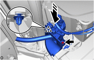

|
Install in this Direction |
Install the wire harness protector.
Attach the clip as shown in the illustration.
Install the wire harness protector with the bolt.
- Torque:
- 13 N*m (133 kgf*cm, 10 ft.*lbf)


|
Ground Wire |

|
Connector |
Connect the wire harness (w/o Power Slide Door).
Connect the 2 connectors.
Install the ground wire with the ground bolt.
- Torque:
- 10 N*m (102 kgf*cm, 7 ft.*lbf)
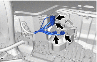
Connect the 4 connectors (w/ Power Slide Door).
51078D
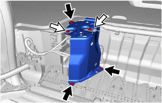
2.INSTALL SIDE STEP BRACKET SUB-ASSEMBLY RH
|
|
Bolt |
|
|
Ground Bolt |
Install the side step bracket sub-assembly with the 3 bolts.
- Torque:
- 7.8 N*m (80 kgf*cm, 69 in.*lbf)
Install the 2 ground wires with the 2 ground bolts.
- Torque:
- 10 N*m (102 kgf*cm, 7 ft.*lbf)
68394A
3.INSTALL SLIDE DOOR LOWER RAIL PLATE RH (w/o Power Slide Door)
68394A
4.INSTALL SLIDE DOOR LOWER RAIL PLATE RH (w/ Power Slide Door)
67917C
5.INSTALL REAR DOOR SCUFF PLATE RH
6.CONNECT CABLE TO NEGATIVE BATTERY TERMINAL (w/ Rear Curtain Shield Airbag)
7. INITIALIZATION AFTER RECONNECTING BATTERY TERMINAL (w/ Rear Curtain Shield Airbag)
- HINT:
-
When disconnecting and reconnecting the battery, there is an automatic learning function that completes learning when the respective system is used.
8.INSPECT SRS WARNING LIGHT (w/ Rear Curtain Shield Airbag)
9. PERFORM DIAGNOSTIC SYSTEM CHECK (w/ Rear Curtain Shield Airbag)
10. INITIALIZE POWER SLIDE DOOR SYSTEM (w/ Power Slide Door)
11. CHECK POWER SLIDE DOOR SYSTEM (w/ Power Slide Door)