DOOR LOCK POWER DOOR LOCK CONTROL SYSTEM TERMINALS OF ECU
CHECK INSTRUMENT PANEL JUNCTION BLOCK ASSEMBLY AND MAIN BODY ECU (MULTIPLEX NETWORK BODY ECU)
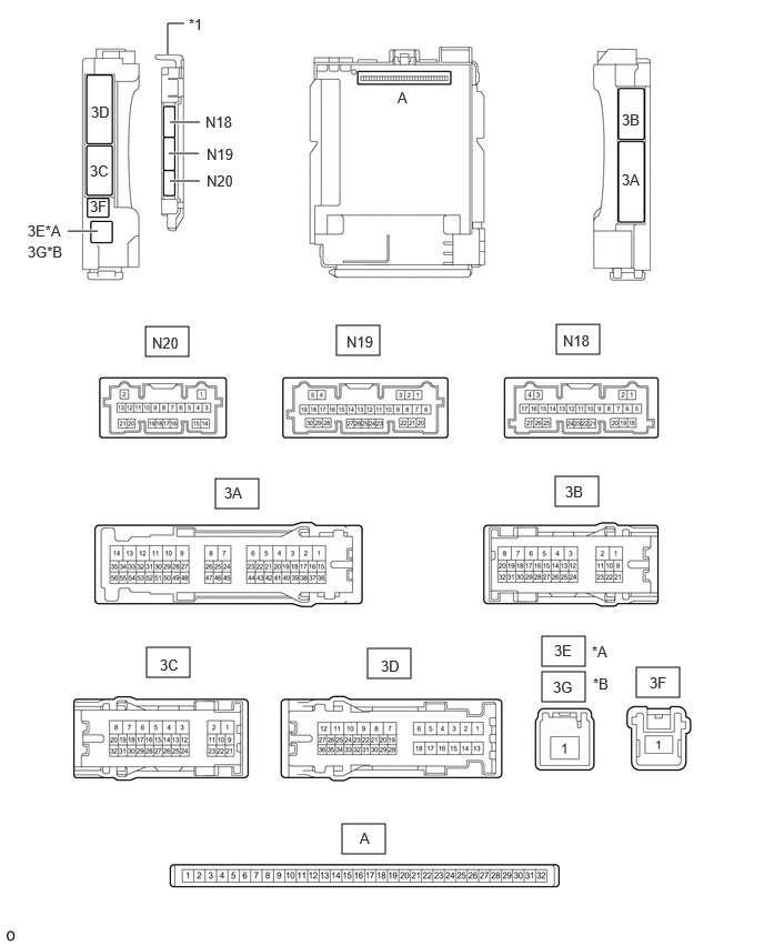
| *A | for LHD | *B | for RHD |
| *1 | Main Body ECU (Multiplex Network Body ECU) | - | - |
Remove the main body ECU (multiplex network body ECU) from the instrument panel junction block assembly.
Reconnect the instrument panel junction block assembly connectors.
Measure the voltage and resistance according to the value(s) in the table below.
| Tester Connection | Wiring Color | Input/Output | Terminal Description | Condition | Specified Condition | Related Data List Item |
|---|---|---|---|---|---|---|
| A-11 (GND1) - Body ground | - | - | Ground | Always | Below 1 Ω | - |
| A-30 (ACC) - Body ground | - | Input | ACC power supply | Ignition switch ACC | 11 to 14 V | ACC SW |
| Ignition switch off | Below 1 V | |||||
| A-31 (BECU) - Body ground | - | Input | Battery power supply | Always | 11 to 14 V | - |
| A-32 (IG) - Body ground | - | Input | IG power supply | Ignition switch ON | 11 to 14 V*1
10.5 to 16 V*2 |
IG SW |
| Ignition switch off | Below 1 V |
*1: w/o Stop and Start System
*2: w/ Stop and Start System
Install the main body ECU (multiplex network body ECU) to the instrument panel junction block assembly.
Measure the voltage and check for pulses according to the value(s) in the table below.
| Tester Connection | Wiring Color | Input/Output | Terminal Description | Condition | Specified Condition | Related Data List Item |
|---|---|---|---|---|---|---|
| N19-1 (FLCY) - Body ground | R - Body ground | Input | Front door courtesy light switch assembly LH input | Front door LH open → closed | Below 1 V → 4.7 to 5.3 V | FL Door Courtesy SW |
| N19-6 (FRCY) - Body ground | R - Body ground | Input | Front door courtesy light switch assembly RH input | Front door RH open → closed | Below 1 V → 4.7 to 5.3 V | FR Door Courtesy SW |
| 3D-24 (LCTY) - Body ground*1 | LA-R - Body ground | Input | Slide door courtesy light switch assembly LH input | Slide door LH open → closed | Below 1 V → 4.7 to 5.3 V | RL Door Courtesy SW |
| 3A-31 (RCTY) - Body ground*2 | LA-G - Body ground | Input | Slide door courtesy light switch assembly RH input | Slide door RH open → closed | Below 1 V → 4.7 to 5.3 V | RR Door Courtesy SW |
| N20-18 (L2) - Body ground | W - Body ground | Input | Driver and front passenger door key-linked lock input | Driver or front passenger door key cylinder turned to neutral position → on (lock) | Pulse generation → Below 1 V | Door Key SW-Lock |
| N20-17 (UL3) - Body ground | Y - Body ground | Input | Driver door key-linked unlock input | Driver door key cylinder turned to neutral position → on (unlock) | Pulse generation → Below 1 V | D Door Key SW-UL |
| N20-19 (UL2) - Body ground*3 | Y - Body ground | Input | Front passenger door key-linked unlock input | Front passenger door key cylinder turned to neutral position → on (unlock) | Pulse generation → Below 1 V | Door Key SW-Unlock |
| 3D-6 (ACT+) - Body ground | LA-LG - Body ground | Output | Door lock motor lock drive output | Door control switch or door key cylinder off → on (lock) | Below 1 V → 11 to 14 V → Below 1 V | - |
| 3B-2 (ACT+) - Body ground | LA-L - Body ground | Output | Door lock motor lock drive output | Door control switch or door key cylinder off → on (lock) | Below 1 V → 11 to 14 V → Below 1 V | - |
| 3B-1 (ACT-) - Body ground | LA-W - Body ground | Output | Door lock motor lock drive output | Door control switch or door key cylinder off → on (unlock) | Below 1 V → 11 to 14 V → Below 1 V | - |
| 3D-9 (ACT-) - Body ground | LA-R - Body ground | Output | Door lock motor lock drive output | Door control switch or door key cylinder off → on (unlock) | Below 1 V → 11 to 14 V → Below 1 V | - |
| 3D-18 (ACT-) - Body ground | LA-L - Body ground | Output | Door lock motor lock drive output | Door control switch or door key cylinder off → on (unlock) | Below 1 V → 11 to 14 V → Below 1 V | - |
| 3B-4 (ACTD) - Body ground | LA-R - Body ground | Output | Driver door lock motor unlock drive output | Door control switch or driver door key cylinder off → on (unlock) | Below 1 V → 11 to 14 V → Below 1 V | - |
| 3B-12 (LSFR) - Body ground | B - Body ground | Input | Front door RH unlock detection switch input | Front door RH locked → unlocked | Pulse generation → Below 1 V | FR Door Lock Pos |
| 3B-13 (LSFL) - Body ground | B - Body ground | Input | Front door LH unlock detection switch input | Front door LH locked → unlocked | Pulse generation → Below 1 V | FL Door Lock Pos |
| N18-20 (LSWR) - Body ground*2 | L - Body ground | Input | Slide door RH unlock detection switch input | Slide door RH locked → unlocked | Pulse generation → Below 1 V | RR-Door Lock Pos SW |
| 3B-14 (LSWL) - Body ground*1 | L - Body ground | Input | Slide door LH unlock detection switch signal | Slide door LH locked → unlocked | Pulse generation → Below 1 V | RL-Door Lock Pos SW |
| 3D-34 (BCTY) - Body ground | L - Body ground | Input | Back door courtesy light switch input | Back door closed | Below 1 V | Back Door Courtesy SW |
| Back door open | Pulse generation | |||||
| N19-9 (ACTG) - Body ground*4 | G - Body ground | Output | Collision door lock release signal | Collision door lock release function does not operate | Below 2 V*5
7.3 to 9.9 V*6 |
- |
| Collision door lock release function operates | Below 1 V | |||||
| 3A-7 (GSW) - Body ground*7 | B - Body ground | Input | Collision detection input | Ignition switch ON | 2.9 to 4.2 V | - |
*1: w/ Slide Door LH
*2: w/ Slide Door RH
*3: w/ Front Passenger Side Door Key Cylinder
*4: w/ Door Control Battery
*5: Door control battery not charged
*6: Door control battery charging or charged
*7: w/ Entry and Start System
CHECK AIRBAG ECU ASSEMBLY