DOOR / HATCH POWER SLIDE DOOR SYSTEM Power Slide Door RH does not Operated Using Any Operation
DESCRIPTION
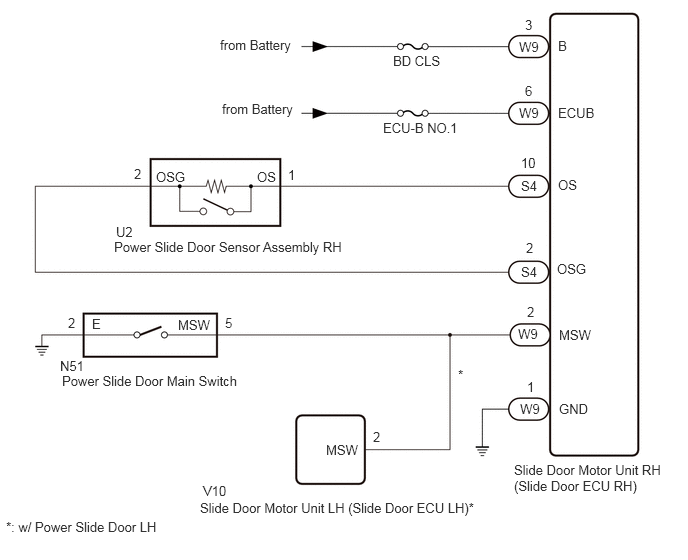
The power slide door main switch signal is sent to the slide door motor unit RH (slide door ECU RH) and slide door motor unit LH (slide door ECU LH)*.
If the power slide door does not operate using any of the operations, a malfunction related to the power slide door operation conditions, power slide door main switch or power slide door sensor assembly RH circuit malfunction is a possible cause.
*: w/ Power Slide Door LH
WIRING DIAGRAM
CAUTION / NOTICE / HINT
- NOTICE:
-
Inspect the fuses for circuits related to this system before performing the following inspection procedure.
PROCEDURE
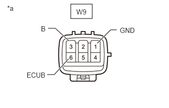
| *a | Front view of wire harness connector
(to Slide Door Motor Unit RH [Slide Door ECU RH]) |
Disconnect the slide door motor unit RH (slide door ECU RH) connector.
Measure the resistance according to the value(s) in the table below.
- Standard Resistance:
Tester Connection Condition Specified Condition W9-1 (GND) - Body ground Always Below 1 Ω
Measure the voltage according to the value(s) in the table below.
- Standard Voltage:
Tester Connection Condition Specified Condition W9-3 (B) - Body ground Always 11 to 14 V W9-6 (ECUB) - Body ground Always 11 to 14 V
- Result:
Proceed to OK NG
OK
NG
Read the Data List according to the display on the GTS.
- Body Electrical > Rear Right Door > Data List
-
Tester Display Measurement Item Normal Condition Reference Value Diagnostic Note PSD Main Switch Power slide door main switch signal ON or OFF ON: Power slide door main switch on
OFF: Power slide door main switch off-
- Body Electrical > Rear Right Door > Data List
-
Tester Display PSD Main Switch - 50003 161 8
- OK:
On the GTS screen, ON or OFF is displayed accordingly.
- Result:
Proceed to OK NG
OK
NG
Read the Data List according to the display on the GTS.
- Body Electrical > Rear Right Door > Data List
-
Tester Display Measurement Item Normal Condition Reference Value Diagnostic Note PSD Touch Sensor Power slide door sensor assembly RH signal OFF, ON or Open OFF: Power slide door sensor assembly RH not pressed
ON: Power slide door sensor assembly RH pressed
Open: Power slide door sensor assembly RH open-
- Body Electrical > Rear Right Door > Data List
-
Tester Display PSD Touch Sensor - 50003 161 5
- OK:
On the GTS screen, ON or OFF is displayed accordingly.
- Result:
Proceed to OK NG
OK
NG
Remove the power slide door sensor assembly RH.
Inspect the power slide door sensor assembly RH.
- Result:
Result Proceed to OK A NG (except Wagon) B NG (for Wagon) C
A
B
C
Disconnect the S4 slide door motor unit RH (slide door ECU RH) connector.
Disconnect the U2 power slide door sensor assembly RH connector.
Measure the resistance according to the value(s) in the table below.
- Standard Resistance:
Tester Connection Condition Specified Condition S4-10 (OS) - U2-1 (OS) Always Below 1 Ω S4-2 (OSG) - U2-2 (OSG) Always Below 1 Ω S4-10 (OS) or U2-1 (OS) - Body ground Always 10 kΩ or higher S4-2 (OSG) or U2-2 (OSG) - Body ground Always 10 kΩ or higher
- Result:
Proceed to OK NG
OK
NG
Remove the power slide door main switch.
Inspect the power slide door main switch.
- Result:
Result Proceed to OK (w/o Power Slide Door LH) A OK (w/ Power Slide Door LH) B NG C
A
B
C
Disconnect the N51 power slide door main switch connector.
Disconnect the W9 slide door motor unit RH (slide door ECU RH) connector.
Measure the resistance according to the value(s) in the table below.
- Standard Resistance:
Tester Connection Condition Specified Condition N51-5 (MSW) - W9-2 (MSW) Always Below 1 Ω N51-2 (E) - Body ground Always Below 1 Ω N51-5 (MSW) or W9-2 (MSW) - Body ground Always 10 kΩ or higher
- Result:
Proceed to OK NG
OK
NG
Disconnect the V10 slide door motor unit LH (slide door ECU LH) connector.
Read the Data List according to the display on the GTS.
- Body Electrical > Rear Right Door > Data List
-
Tester Display Measurement Item Normal Condition Reference Value Diagnostic Note PSD Main Switch Power slide door main switch signal ON or OFF ON: Power slide door main switch on
OFF: Power slide door main switch off-
- Body Electrical > Rear Right Door > Data List
-
Tester Display PSD Main Switch - 50003 161 8
- OK:
On the GTS screen, ON or OFF is displayed accordingly.
- Result:
Proceed to OK NG
OK
NG
Disconnect the N51 power slide door main switch connector.
Disconnect the W9 slide door motor unit RH (slide door ECU RH) connector.
Disconnect the V10 slide door motor unit LH (slide door ECU LH) connector.
Measure the resistance according to the value(s) in the table below.
- Standard Resistance:
Tester Connection Condition Specified Condition N51-5 (MSW) - W9-2 (MSW) Always Below 1 Ω N51-2 (E) - Body ground Always Below 1 Ω N51-5 (MSW) or W9-2 (MSW) - Body ground Always 10 kΩ or higher
- Result:
Proceed to OK NG
OK
NG