SUPPLEMENTAL RESTRAINT SYSTEMS AIRBAG SYSTEM(for Type C) SRS Warning Light does not Come ON
DESCRIPTION
The SRS warning light is located in the combination meter assembly.
When the SRS is normal, the SRS warning light comes on for approximately 6 seconds after the engine switch is turned from off to on (IG), and then goes off automatically.
If there is a malfunction in the SRS, the SRS warning light comes on to inform the driver of a problem.
When terminals TC and CG of the DLC3 are connected, DTCs are output by the blinking of the SRS warning light.
The SRS is equipped with a voltage-increase circuit (DC-DC converter) in the airbag sensor assembly in case the source voltage drops.
When the battery voltage drops, the voltage-increase circuit (DC-DC converter) functions to increase the voltage of the SRS to normal voltage.
A malfunction in this circuit is not recorded in the airbag sensor assembly. The SRS warning light automatically goes off when the source voltage returns to normal.
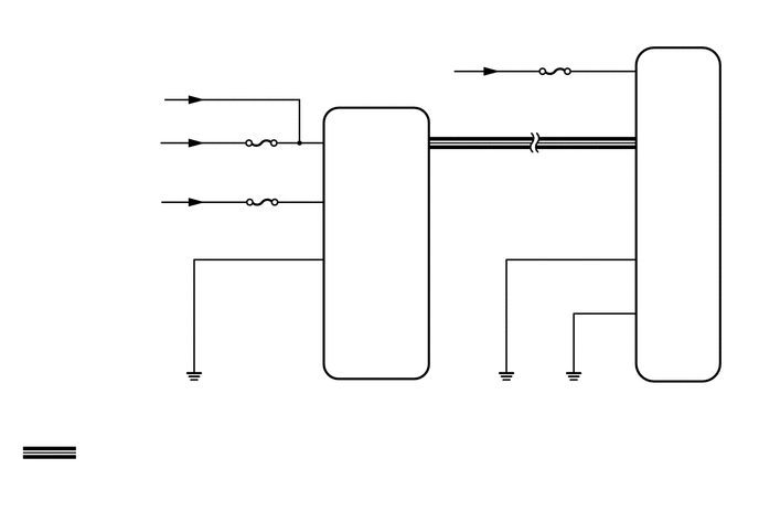
The signal to illuminate the SRS warning light is transmitted from the airbag sensor assembly to the combination meter assembly through the CAN communication system.
WIRING DIAGRAM
CAUTION / NOTICE / HINT
- NOTICE:
- ·
After the engine switch is turned off, there may be a waiting time before disconnecting the negative (-) battery terminal.
·When disconnecting and reconnecting the battery
- HINT:
-
When disconnecting and reconnecting the battery, there is an automatic learning function that completes learning when the respective system is used.
·After replacing the airbag sensor assembly, refer to initialization.
·Inspect the fuses for circuits related to this system before performing the following procedure.
·When replacing the combination meter assembly, always replace it with a new one. If a combination meter assembly which was installed to another vehicle is used, the information stored in it will not match the information from the vehicle and a DTC may be stored.
PROCEDURE
Measure the battery voltage.
- Standard voltage:
11 to 14 V
- HINT:
-
It may be possible to tell whether the battery is discharged by operating the horn.
-
If the voltage is below 11 V, recharge or replace the battery before proceeding to the next step.
- Result:
Proceed to OK NG
OK
NG
Turn the engine switch off.
Disconnect the cable from the negative (-) battery terminal, and wait for at least 90 seconds.
Check that the connector is properly connected to the combination meter assembly.
- OK:
The connector is properly connected.
- HINT:
-
If the connector is not properly connected, reconnect the connector and proceed to the next inspection.
Disconnect the connector from the combination meter assembly.
Check that the terminals of the connector are not deformed or damaged.
- OK:
The terminals are not deformed or damaged.
- Result:
Proceed to OK NG
OK
NG
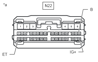
| *a | Front view of wire harness connector
(to Combination Meter Assembly) |
Connect the cable to the negative (-) battery terminal, and wait for at least 2 seconds.
Turn the engine switch on (IG).
Measure the voltage according to the value(s) in the table below.
- Standard Voltage:
w/o Stop and Start System Tester Connection Condition Specified Condition N22-38 (IG+) - Body ground Engine switch on (IG) 11 to 14 V N22-22 (B) - Body ground Always 11 to 14 V
w/ Stop and Start System Tester Connection Condition Specified Condition N22-38 (IG+) - Body ground Engine switch on (IG) 10.5 to 16 V N22-22 (B) - Body ground Always 11 to 14 V
Measure the resistance according to the value(s) in the table below.
- Standard Resistance:
Tester Connection Condition Specified Condition N22-23 (ET) - Body ground Always Below 1 Ω
- Result:
Proceed to OK NG
OK
NG
Disconnect the cable from the negative (-) battery terminal, and wait for at least 90 seconds.
Connect the connector to the combination meter assembly.
Connect the cable to the negative (-) battery terminal, and wait for at least 2 seconds.
Turn the engine switch on (IG) and check the SRS warning light condition.
- OK:
After the primary check period, the SRS warning light turns off for approximately 10 seconds and then turns back on.
- HINT:
-
The primary check period is approximately 6 seconds after the engine switch is turned on (IG).
- Result:
Proceed to OK NG
OK
NG