TELEMATICS TELEPHONE ANTENNA INSTALLATION
PROCEDURE

 86300C
1.INSTALL NO. 2 AMPLIFIER ANTENNA ASSEMBLY
86300C
1.INSTALL NO. 2 AMPLIFIER ANTENNA ASSEMBLY
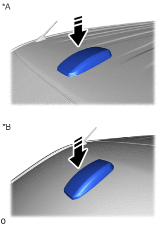
| *A | for Standard Roof |
| *B | for High Roof |

|
Install in this Direction |
Install a new No. 2 amplifier antenna assembly as shown in the illustration.
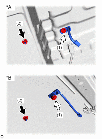
| *A | for Standard Roof |
| *B | for High Roof |

|
Bolt |

|
Nut |
Install a new bolt and nut in the order shown in the illustration.
- Torque:
- Bolt : 9.5 N*m (97 kgf*cm, 84 in.*lbf)
- Nut : 15 N*m (153 kgf*cm, 11 ft.*lbf)
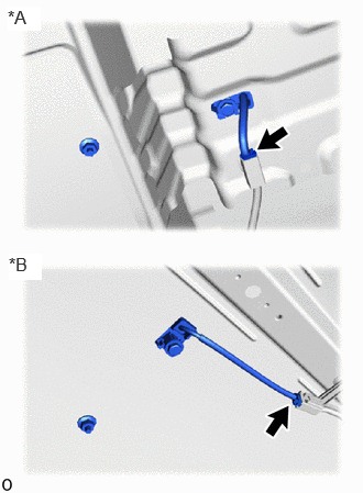
| *A | for Standard Roof |
| *B | for High Roof |
Connect the connector.
2.INSTALL TIRE PRESSURE WARNING ECU WITH WINDSHIELD HEADER PANEL DAMPER SUB-ASSEMBLY RH (for Standard Roof)
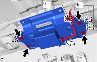
| *a | Clamp |
| *b | Guide |
|
|
Bolt |
|
|
Connector |
Attach the guide and clip to temporarily install the tire pressure warning ECU with windshield header panel damper sub-assembly RH.
Install the 4 bolts.
- Torque:
- 10 N*m (102 kgf*cm, 7 ft.*lbf)
Attach the wire harness clamp.
Connect the connector.
3.INSTALL ROOF HEADLINING ASSEMBLY
4.CONNECT CABLE TO NEGATIVE BATTERY TERMINAL
5. INITIALIZATION AFTER RECONNECTING BATTERY TERMINAL
- HINT:
-
When disconnecting and reconnecting the battery, there is an automatic learning function that completes learning when the respective system is used.
6. PERFORM DIAGNOSTIC SYSTEM CHECK
7.CHECK SRS WARNING LIGHT
8.INSPECT SEAT BELT WARNING SYSTEM