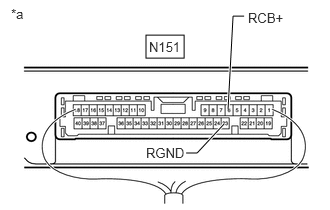
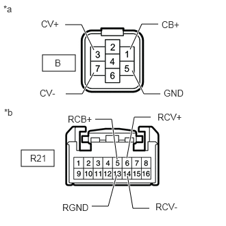
RM35X0E _56 Audio / Visual / Telematics _079315 PARK ASSIST / MONITORING _0396274 PANORAMIC VIEW MONITOR SYSTEM J

PARK ASSIST / MONITORING  PANORAMIC VIEW MONITOR SYSTEM  Image from Camera for Panoramic View Monitor is Abnormal  


DESCRIPTION

The display signal from each television camera is transmitted to the radio and display receiver assembly via the parking assist ECU.

WIRING DIAGRAM
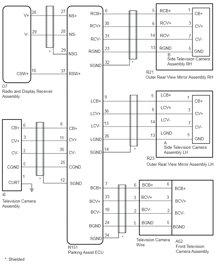
E419398E01
2.292,5.448 2.906,5.646 0.615,0.198 10 false CGND 2.99,7.813 3.604,8.01 0.615,0.198 10 false SGND 2.323,5.99 2.938,6.188 0.615,0.198 10 false SGND 2.99,4.958 3.604,5.156 0.615,0.198 10 false SGND 2.979,2.083 3.594,2.281 0.615,0.198 10 false SGND 0.073,2.938 1.792,3.302 1.719,0.365 10 false Radio and Display Receiver Assembly 5.833,8.073 7.083,8.604 1.25,0.531 10 false Front Television Camera Assembly 4.833,2.469 7.156,2.719 2.323,0.25 10 false Outer Rear View Mirror Assembly RH 5.552,1.865 7.021,2.271 1.469,0.406 10 false Side Television Camera Assembly RH 4.865,5.354 7.156,5.625 2.292,0.271 10 false Outer Rear View Mirror Assembly LH 5.438,4.792 6.906,5.125 1.469,0.333 10 false Side Television Camera Assembly LH 0.073,6.573 1.24,6.938 1.167,0.365 10 false Television Camera Assembly 2.26,8.271 3.615,8.563 1.354,0.292 10 false Parking Assist ECU 3,0.365 3.615,0.563 0.615,0.198 10 false RCB+ 2.979,0.771 3.594,0.969 0.615,0.198 10 false RCV+ 3.01,1.208 3.625,1.406 0.615,0.198 10 false RCV- 2.938,1.615 3.552,1.813 0.615,0.198 10 false RGND 2.281,0.438 2.896,0.635 0.615,0.198 10 false NS+ 2.292,1.052 2.906,1.25 0.615,0.198 10 false NS- 2.271,1.698 2.885,1.896 0.615,0.198 10 false NSG 0.792,0.427 1.406,0.625 0.615,0.198 10 false V+ 0.813,1.052 1.427,1.25 0.615,0.198 10 false V- 0.063,2.771 0.677,2.969 0.615,0.198 10 false O7 1.052,0.323 1.313,0.521 0.26,0.198 10 false 28 1.063,0.969 1.292,1.167 0.229,0.198 10 false 29 2.021,0.292 2.229,0.5 0.208,0.208 10 false 27 2.021,0.948 2.25,1.146 0.229,0.198 10 false 28 2.031,1.573 2.26,1.792 0.229,0.219 10 false 29 2.26,8.104 2.875,8.302 0.615,0.198 10 false N151 3.469,7.698 3.844,7.875 0.375,0.177 10 false 34 3.479,7.281 3.854,7.458 0.375,0.177 10 false 24 2.281,4.969 2.896,5.167 0.615,0.198 10 false CV- 2.281,4.542 2.896,4.74 0.615,0.198 10 false CV+ 2.292,4.167 2.906,4.365 0.615,0.198 10 false CB+ 0.375,4.146 0.99,4.344 0.615,0.198 10 false CB+ 0.375,4.583 0.99,4.781 0.615,0.198 10 false CV+ 0.385,4.979 1,5.177 0.615,0.198 10 false CV- 0.24,5.448 0.854,5.646 0.615,0.198 10 false CGND 3.479,6.854 3.854,7.031 0.375,0.177 10 false 10 3.49,6 3.865,6.177 0.375,0.177 10 false 7 5.542,6.01 5.917,6.188 0.375,0.177 10 false 6 5.531,6.448 5.906,6.625 0.375,0.177 10 false 3 5.552,6.885 5.927,7.063 0.375,0.177 10 false 2 5.542,7.281 5.917,7.458 0.375,0.177 10 false 5 5.823,7.906 6.438,8.104 0.615,0.198 10 false A52 0.771,4.063 1.146,4.24 0.375,0.177 10 false 6 0.781,4.458 1.156,4.635 0.375,0.177 10 false 3 0.771,4.906 1.146,5.083 0.375,0.177 10 false 2 0.771,5.344 1.146,5.521 0.375,0.177 10 false 5 0.083,6.354 0.698,6.552 0.615,0.198 10 false i6 2.958,7.396 3.573,7.594 0.615,0.198 10 false BGND 5.74,7.427 6.354,7.625 0.615,0.198 10 false BGND 3.01,6.938 3.625,7.135 0.615,0.198 10 false BCV- 2.969,6.583 3.583,6.781 0.615,0.198 10 false BCV+ 3,6.135 3.615,6.333 0.615,0.198 10 false BCB+ 5.802,6.156 6.417,6.354 0.615,0.198 10 false BCB+ 5.813,6.573 6.427,6.771 0.615,0.198 10 false BCV+ 5.802,6.969 6.417,7.167 0.615,0.198 10 false BCV- 2,5.875 2.323,6.052 0.323,0.177 10 false 12 2.01,5.292 2.333,5.469 0.323,0.177 10 false 25 1.979,4.865 2.302,5.042 0.323,0.177 10 false 35 1.979,4.479 2.302,4.656 0.323,0.177 10 false 11 2,4.021 2.323,4.198 0.323,0.177 10 false 8 3.49,0.271 3.813,0.448 0.323,0.177 10 false 6 3.469,0.688 3.792,0.865 0.323,0.177 10 false 30 3.479,1.104 3.802,1.281 0.323,0.177 10 false 31 3.479,1.521 3.802,1.698 0.323,0.177 10 false 23 3.479,1.979 3.802,2.156 0.323,0.177 10 false 32 5.302,0.271 5.917,0.469 0.615,0.198 10 false RCB+ 5.313,0.677 5.927,0.875 0.615,0.198 10 false RCV+ 5.313,1.094 5.927,1.292 0.615,0.198 10 false RCV- 5.292,1.51 5.906,1.708 0.615,0.198 10 false RGND 4.854,2.302 5.198,2.542 0.344,0.24 10 false R21 5.052,0.26 5.406,0.573 0.354,0.313 10 false 5 5.052,0.698 5.406,1.01 0.354,0.313 10 false 6 4.99,1.083 5.344,1.396 0.354,0.313 10 false 14 5,1.49 5.354,1.802 0.354,0.313 10 false 13 4.875,5.156 5.219,5.396 0.344,0.24 10 false R23 3,4.531 3.615,4.729 0.615,0.198 10 false LGND 3.021,4.083 3.635,4.281 0.615,0.198 10 false LCV- 3,3.677 3.615,3.875 0.615,0.198 10 false LCV+ 3.01,3.26 3.625,3.458 0.615,0.198 10 false LCB+ 3.469,3.125 3.792,3.302 0.323,0.177 10 false 9 3.458,3.594 3.781,3.771 0.323,0.177 10 false 36 3.448,4 3.771,4.177 0.323,0.177 10 false 13 3.469,4.417 3.792,4.594 0.323,0.177 10 false 26 3.458,4.854 3.781,5.031 0.323,0.177 10 false 14 5.333,3.063 5.948,3.26 0.615,0.198 10 false LCB+ 5.333,3.479 5.948,3.677 0.615,0.198 10 false LCV+ 5.344,3.885 5.958,4.083 0.615,0.198 10 false LCV- 5.333,4.323 5.948,4.521 0.615,0.198 10 false LGND 5.021,3.083 5.375,3.396 0.354,0.313 10 false 5 5.042,3.542 5.396,3.854 0.354,0.313 10 false 6 4.99,3.948 5.344,4.26 0.354,0.313 10 false 14 4.99,4.396 5.344,4.708 0.354,0.313 10 false 13 1.625,1.646 1.781,1.844 0.156,0.198 10 false * 4.375,1.99 4.531,2.188 0.156,0.198 10 false * 4.448,4.875 4.604,5.073 0.156,0.198 10 false * 1.302,5.854 1.458,6.052 0.156,0.198 10 false * 4.042,7.781 4.198,7.979 0.156,0.198 10 false * 0.156,8.5 1.052,8.75 0.896,0.25 10 false *: Shielded 6.24,0.24 6.625,0.458 0.385,0.219 10 false 1 5.563,1.729 5.948,1.948 0.385,0.219 10 false B 6.26,0.677 6.646,0.896 0.385,0.219 10 false 3 6.26,1.115 6.646,1.333 0.385,0.219 10 false 7 6.26,1.521 6.646,1.74 0.385,0.219 10 false 5 6.219,4.375 6.604,4.594 0.385,0.219 10 false 5 6.25,3.99 6.635,4.208 0.385,0.219 10 false 7 6.24,3.552 6.625,3.771 0.385,0.219 10 false 3 6.208,3.146 6.594,3.365 0.385,0.219 10 false 1 5.438,4.646 5.823,4.865 0.385,0.219 10 false A 3.479,6.427 3.854,6.604 0.375,0.177 10 false 33 6.458,0.365 6.875,0.552 0.417,0.188 10 false CB+ 6.469,0.781 6.885,0.969 0.417,0.188 10 false CV+ 6.479,1.219 6.896,1.406 0.417,0.188 10 false CV- 6.448,1.615 6.865,1.802 0.417,0.188 10 false GND 6.458,3.26 6.875,3.448 0.417,0.188 10 false CB+ 6.469,3.677 6.885,3.865 0.417,0.188 10 false CV+ 6.469,4.125 6.885,4.313 0.417,0.188 10 false CV- 6.458,4.51 6.875,4.698 0.417,0.188 10 false GND 2.021,2.26 2.25,2.479 0.229,0.219 10 false 37 2.281,2.354 2.896,2.552 0.615,0.198 10 false RSW+ 0.552,2.354 1.167,2.552 0.615,0.198 10 false CSW+ 1.042,2.25 1.271,2.448 0.229,0.198 10 false 18 4.521,7.854 5.688,8.385 1.167,0.531 10 false Television Camera Wire 4.719,6.042 5.333,6.24 0.615,0.198 10 false BCB+ 4.688,6.448 5.302,6.646 0.615,0.198 10 false BCV+ 4.698,6.854 5.313,7.052 0.615,0.198 10 false BCV- 4.698,7.292 5.313,7.49 0.615,0.198 10 false BGND 4.448,6.042 4.823,6.219 0.375,0.177 10 false 6 4.438,6.458 4.813,6.635 0.375,0.177 10 false 3 4.448,6.896 4.823,7.073 0.375,0.177 10 false 2 4.438,7.302 4.813,7.479 0.375,0.177 10 false 5 0.281,5.958 0.896,6.156 0.615,0.198 10 false CURT 0.75,5.76 1.125,5.938 0.375,0.177 10 false 1

CAUTION / NOTICE / HINT

NOTICE:
·

When the "!" mark is displayed on the multi-display after the cable is disconnected from the negative (-) battery terminal, correct the steering angle neutral point.

Click hereAudio / Visual / Telematics>PARK ASSIST / MONITORING>PANORAMIC VIEW MONITOR SYSTEM>INITIALIZATION

·

Depending on the parts that are replaced or operations that are performed during vehicle inspection or maintenance, calibration of other systems as well as the panoramic view monitor system may be needed.

Click hereAudio / Visual / Telematics>PARK ASSIST / MONITORING>PANORAMIC VIEW MONITOR SYSTEM>CALIBRATION


HINT:
Images may be unclear even in normal conditions if:
·

Electrical devices are used in the cabin (noise may occur in the image).

·

The camera lens is frosted over (the image immediately after turning the engine switch on (IG) may be blurred or darker than normal).

·

The camera lens is dirty with snow, mud, etc.

·

A strong beam of light, such as a sunbeam or headlight, hits the camera.

·

It is too dark around the camera (at night, etc.).

·

The ambient temperature around the camera is either too high or too low.

·

The vehicle is tilted at a steep angle.

·

The television camera assembly lens is scratched.

·

The television camera assembly lens has drops of water on it or the humidity is high.

·

When the camera is used under fluorescent lights, sodium lights, or mercury lights, etc., the lights and the illuminated area may appear to flicker.


PROCEDURE

1.CHECK PANORAMIC VIEW MONITOR SYSTEM
a.

Check if the same malfunction occurs when the panoramic view monitor screen is displayed.


Result:
Result Proceed to
Rear view screen is not displayed. A
Front view screen is not displayed. B
Side monitor screen (LH side) is not displayed. C
Side monitor screen (RH side) is not displayed. D
Panoramic view monitor screen is not displayed. E


A

2.CHECK HARNESS AND CONNECTOR (PARKING ASSIST ECU - TELEVISION CAMERA ASSEMBLY)

B

6.INSPECT TELEVISION CAMERA WIRE

C

11.CHECK HARNESS AND CONNECTOR (PARKING ASSIST ECU - OUTER REAR VIEW MIRROR ASSEMBLY LH)

D

17.CHECK HARNESS AND CONNECTOR (PARKING ASSIST ECU - OUTER REAR VIEW MIRROR ASSEMBLY RH)

E

23.CHECK HARNESS AND CONNECTOR (PARKING ASSIST ECU - RADIO AND DISPLAY RECEIVER ASSEMBLY)
2.CHECK HARNESS AND CONNECTOR (PARKING ASSIST ECU - TELEVISION CAMERA ASSEMBLY)
a.

Disconnect the N151 parking assist ECU connector.


b.

Disconnect the i6 television camera assembly connector.


c.

Measure the resistance according to the value(s) in the table below.

Standard Resistance:
Tester Connection Condition Specified Condition
N151-8 (CB+) - i6-6 (CB+) Always Below 1 Ω
N151-11 (CV+) - i6-3 (CV+) Always Below 1 Ω
N151-35 (CV-) - i6-2 (CV-) Always Below 1 Ω
N151-25 (CGND) - i6-5 (CGND) Always Below 1 Ω
N151-12 (SGND) - Body ground Always Below 1 Ω
i6-1 (CURT) - Body ground Always Below 1 Ω
N151-8 (CB+) or i6-6 (CB+) - Body ground Always 10 kΩ or higher
N151-11 (CV+) or i6-3 (CV+) - Body ground Always 10 kΩ or higher
N151-35 (CV-) or i6-2 (CV-) - Body ground Always 10 kΩ or higher
N151-25 (CGND) or i6-5 (CGND) - Body ground Always 10 kΩ or higher


Result:
Proceed to
OK
NG


OK

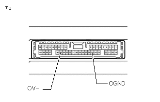
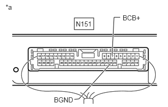
3.CHECK PARKING ASSIST ECU (CV-, CGND)

NG

REPAIR OR REPLACE HARNESS OR CONNECTOR

3.CHECK PARKING ASSIST ECU (CV-, CGND)
a.
E330226C73
2.302,1.792 2.073,1.792 2.073,1.792 1.979,1.146 true 0.917,1.917 1.083,1.917 1.083,1.917 1.292,1.135 true 0.115,0.094 0.427,0.25 0.313,0.156 10 false *a 2.344,1.719 2.813,1.927 0.469,0.208 10 false CGND 0.594,1.823 1.094,1.979 0.5,0.156 10 false CV-
*a Component without harness connected
(Parking Assist ECU)


Disconnect the N151 parking assist ECU connector.


b.

Measure the resistance according to the value(s) in the table below.

Standard Resistance:
Tester Connection Condition Specified Condition
35 (CV-) - Body ground Always Below 1 Ω
25 (CGND) - Body ground Always Below 1 Ω


Result:
Proceed to
OK
NG


OK

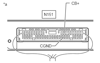
4.CHECK PARKING ASSIST ECU (CB+, CGND)

NG

4.CHECK PARKING ASSIST ECU (CB+, CGND)
a.
E348000C27
1.448,0.365 1.917,0.635 0.469,0.271 2.208,1.146 2.271,0.104 2.271,0.104 2.396,0.104 true 2.177,1.292 1.896,1.594 1.896,1.594 1.781,1.594 true 1.51,0.417 1.885,0.573 0.375,0.156 10 false N151 0.115,0.063 0.313,0.24 0.198,0.177 10 false *a 2.458,0.031 2.771,0.188 0.313,0.156 10 false CB+ 1.375,1.51 1.792,1.667 0.417,0.156 10 false CGND
*a Component with harness connected
(Parking Assist ECU)


Disconnect the television camera assembly.


b.

Measure the resistance according to the value(s) in the table below.

Standard Resistance:
Tester Connection Condition Specified Condition
N151-25 (CGND) - Body ground Always Below 1 Ω


c.

Measure the voltage according to the value(s) in the table below.

Standard Voltage:
Tester Connection Switch Condition Specified Condition
N151-8 (CB+) - N151-25 (CGND) Engine switch on (IG) 5.5 to 7.05 V
N151-8 (CB+) - N151-25 (CGND) Engine switch off Below 1 V


Result:
Proceed to
OK
NG


OK

5.CHECK TELEVISION CAMERA ASSEMBLY (CV+, CGND)

NG

5.CHECK TELEVISION CAMERA ASSEMBLY (CV+, CGND)
a.

Using an oscilloscope, check the waveform of the television camera assembly.

HINT:

A waterproof connector is used for the television camera assembly. Therefore, inspect the waveform at the parking assist ECU with the connector connected.
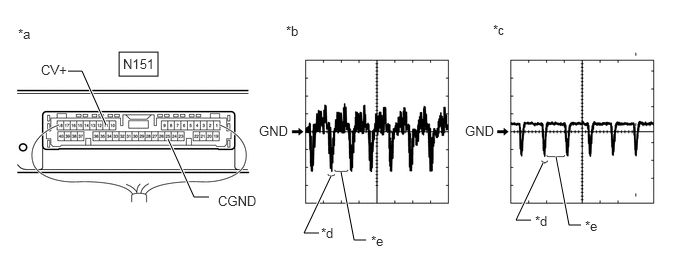

E349540C06
1.24,0.542 1.646,0.792 0.406,0.25 1.104,1.302 0.854,0.74 0.854,0.74 0.708,0.74 true 2.177,2.052 2.021,2.052 2.021,2.052 1.75,1.448 true 3.323,2.427 3.167,2.427 3.167,2.427 3.448,1.833 true 3.813,2.5 3.688,2.5 3.688,2.5 3.552,1.792 true 5.531,2.292 5.375,2.292 5.375,2.292 5.656,1.698 true 6.052,2.344 5.927,2.344 5.927,2.344 5.792,1.635 true 1.281,0.583 1.688,0.74 0.406,0.156 10 false N151 0.188,0.271 0.385,0.448 0.198,0.177 10 false *a 0.427,0.646 0.792,0.813 0.365,0.167 10 false CV+ 2.271,2.01 2.688,2.177 0.417,0.167 10 false CGND 2.979,0.24 3.177,0.417 0.198,0.177 10 false *b 2.698,1.281 3.052,1.448 0.354,0.167 10 false GND 5.135,0.229 5.333,0.406 0.198,0.177 10 false *c 4.844,1.281 5.198,1.448 0.354,0.167 10 false GND 3.344,2.344 3.542,2.521 0.198,0.177 10 false *d 3.865,2.427 4.063,2.604 0.198,0.177 10 false *e 5.573,2.219 5.771,2.396 0.198,0.177 10 false *d 6.094,2.271 6.292,2.448 0.198,0.177 10 false *e
*a Component with harness connected
(Parking Assist ECU)
*b Waveform 1 (camera lens not covered, displaying an image)
*c Waveform 2 (camera lens covered, blacking out the screen) *d Synchronization Signal
*e Video Waveform - -


HINT:
·

The video waveform changes according to the image sent by the television camera assembly.

·

The video waveform is constantly output when the engine switch is on (ACC).


Measurement Condition
Item Content
Terminal No. (Symbol) N151-11 (CV+) - N151-25 (CGND)
Tool Setting 200 mV/DIV., 50 μsec./DIV.
Condition Engine switch on (IG), panoramic view monitor switch on

OK:

Waveform is similar to that shown in the illustration.


Result:
Proceed to
OK
NG


OK

NG

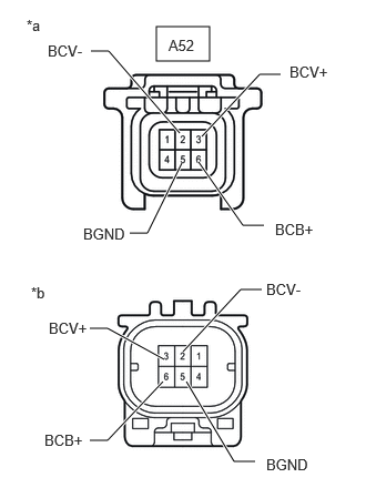
6.INSPECT TELEVISION CAMERA WIRE
a.
E419395C01
1.469,0.25 1.969,0.573 0.5,0.323 2.479,2.115 2.281,2.115 2.281,2.115 1.865,1.521 true 2.635,0.698 2.438,0.698 2.438,0.698 1.896,1.281 true 1.708,1.531 1.385,2.188 1.385,2.188 1.219,2.188 true 1.688,1.25 1.021,0.479 1.021,0.479 0.854,0.479 true 1.531,3.583 1.01,4.135 1.01,4.135 0.844,4.135 true 1.542,3.375 1.01,3.083 1.01,3.083 0.844,3.083 true 2.458,2.719 2.26,2.719 2.26,2.719 1.719,3.302 true 2.396,4.333 2.198,4.333 2.198,4.333 1.75,3.583 true 1.583,0.344 2.042,0.542 0.458,0.198 10 false A52 2.583,2.073 3.156,2.24 0.573,0.167 10 false BCB+ 0.781,2.115 1.354,2.281 0.573,0.167 10 false BGND 0.448,0.396 1.021,0.563 0.573,0.167 10 false BCV- 2.719,0.594 3.292,0.76 0.573,0.167 10 false BCV+ 0.458,3 1.031,3.167 0.573,0.167 10 false BCV+ 0.417,4.052 0.99,4.219 0.573,0.167 10 false BCB+ 2.5,2.635 3.073,2.802 0.573,0.167 10 false BCV- 2.5,4.281 3.073,4.448 0.573,0.167 10 false BGND 0.25,0.156 0.823,0.323 0.573,0.167 10 false *a 0.292,2.667 0.865,2.833 0.573,0.167 10 false *b
*a Front view of television camera wire
(to Front Television Camera Assembly)
*b Front view of television camera wire
(to Vehicle Harness Connector)


Remove the television camera wire.

Click hereAudio / Visual / Telematics>PARK ASSIST / MONITORING>TELEVISION CAMERA (for Front)>REMOVAL


b.

Measure the resistance according to the value(s) in the table below.

Standard Resistance:
Tester Connection Condition Specified Condition
A52-6 (BCB+) - 6 (BCB+) Always Below 1 Ω
A52-3 (BCV+) - 3 (BCV+) Always Below 1 Ω
A52-2 (BCV-) - 2 (BCV+) Always Below 1 Ω
A52-5 (BGND) - 5 (BGND) Always Below 1 Ω


Result:
Proceed to
OK
NG


OK

7.CHECK HARNESS AND CONNECTOR (PARKING ASSIST ECU - FRONT TELEVISION CAMERA ASSEMBLY)

NG

7.CHECK HARNESS AND CONNECTOR (PARKING ASSIST ECU - FRONT TELEVISION CAMERA ASSEMBLY)
a.

Disconnect the N151 parking assist ECU connector.


b.

Disconnect the A52 front television camera assembly connector.


c.

Measure the resistance according to the value(s) in the table below.

Standard Resistance:
Tester Connection Condition Specified Condition
N151-7 (BCB+) - A52-6 (BCB+) Always Below 1 Ω
N151-33 (BCV+) - A52-3 (BCV+) Always Below 1 Ω
N151-10 (BCV-) - A52-2 (BCV-) Always Below 1 Ω
N151-24 (BGND) - A52-5 (BGND) Always Below 1 Ω
N151-34 (SGND) - Body ground Always Below 1 Ω
N151-7 (BCB+) or A52-6 (BCB+) - Body ground Always 10 kΩ or higher
N151-33 (BCV+) or A52-3 (BCV+) - Body ground Always 10 kΩ or higher
N151-10 (BCV-) or A52-2 (BCV-) - Body ground Always 10 kΩ or higher
N151-24 (BGND) or A52-5 (BGND) - Body ground Always 10 kΩ or higher


Result:
Proceed to
OK
NG


OK

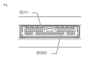
8.CHECK PARKING ASSIST ECU (BCV-, BGND)

NG

REPAIR OR REPLACE HARNESS OR CONNECTOR

8.CHECK PARKING ASSIST ECU (BCV-, BGND)
a.
E330226C74
1.729,1.802 1.896,1.802 1.896,1.802 2.042,1.156 true 1.073,0.427 1.24,0.427 1.24,0.427 1.406,0.979 true 0.115,0.094 0.427,0.25 0.313,0.156 10 false *a 1.24,1.708 1.75,1.906 0.51,0.198 10 false BGND 0.667,0.344 1.167,0.5 0.5,0.156 10 false BCV-
*a Component without harness connected
(Parking Assist ECU)


Disconnect the N151 parking assist ECU connector.


b.

Measure the resistance according to the value(s) in the table below.

Standard Resistance:
Tester Connection Condition Specified Condition
24 (BGND) - Body ground Always Below 1 Ω
10 (BCV-) - Body ground Always Below 1 Ω


Result:
Proceed to
OK
NG


OK

9.CHECK PARKING ASSIST ECU (BCB+, BGND)

NG

9.CHECK PARKING ASSIST ECU (BCB+, BGND)
a.
E348000C28
1.521,0.365 1.917,0.604 0.396,0.24 2.292,1.135 2.333,0.354 2.333,0.354 2.458,0.354 true 2.26,1.302 1.615,2.021 1.615,2.021 1.521,2.031 true 1.552,0.406 1.927,0.573 0.375,0.167 10 false N151 0.115,0.063 0.313,0.24 0.198,0.177 10 false *a 2.51,0.281 2.927,0.438 0.417,0.156 10 false BCB+ 1.104,1.958 1.521,2.115 0.417,0.156 10 false BGND
*a Component with harness connected
(Parking Assist ECU)


Measure the resistance according to the value(s) in the table below.

Standard Resistance:
Tester Connection Condition Specified Condition
N151-24 (BGND) - Body ground Always Below 1 Ω


b.

Measure the voltage according to the value(s) in the table below.

Standard Voltage:
Tester Connection Switch Condition Specified Condition
N151-7 (BCB+) - N151-24 (BGND) Engine switch on (IG) 5.5 to 7.05 V
N151-7 (BCB+) - N151-24 (BGND) Engine switch off Below 1 V


Result:
Proceed to
OK
NG


OK

10.CHECK FRONT TELEVISION CAMERA ASSEMBLY (BCV+, BGND)

NG

10.CHECK FRONT TELEVISION CAMERA ASSEMBLY (BCV+, BGND)
a.

Using an oscilloscope, check the waveform of the front television camera assembly.

HINT:

A waterproof connector is used for the front television camera assembly. Therefore, inspect the waveform at the parking assist ECU with the connector connected.
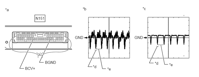

E349540C07
1.25,0.542 1.625,0.792 0.375,0.25 0.865,2.49 0.708,2.49 0.708,2.49 1.198,1.427 true 1.573,2.271 1.417,2.271 1.417,2.271 1.813,1.427 true 3.323,2.427 3.167,2.427 3.167,2.427 3.448,1.833 true 3.813,2.5 3.688,2.5 3.688,2.5 3.552,1.792 true 5.531,2.292 5.375,2.292 5.375,2.292 5.656,1.698 true 6.052,2.344 5.927,2.344 5.927,2.344 5.792,1.635 true 1.281,0.583 1.635,0.75 0.354,0.167 10 false N151 0.188,0.271 0.385,0.448 0.198,0.177 10 false *a 0.906,2.406 1.344,2.583 0.438,0.177 10 false BCV+ 1.625,2.188 2.042,2.354 0.417,0.167 10 false BGND 2.979,0.24 3.177,0.417 0.198,0.177 10 false *b 2.698,1.281 3.052,1.448 0.354,0.167 10 false GND 5.135,0.229 5.333,0.406 0.198,0.177 10 false *c 4.844,1.281 5.198,1.448 0.354,0.167 10 false GND 3.344,2.344 3.542,2.521 0.198,0.177 10 false *d 3.865,2.427 4.063,2.604 0.198,0.177 10 false *e 5.573,2.219 5.771,2.396 0.198,0.177 10 false *d 6.094,2.271 6.292,2.448 0.198,0.177 10 false *e
*a Component with harness connected
(Parking Assist ECU)
*b Waveform 1 (camera lens not covered, displaying an image)
*c Waveform 2 (camera lens covered, blacking out the screen) *d Synchronization Signal
*e Video Waveform - -


HINT:
·

The video waveform changes according to the image sent by the front television camera assembly.

·

The video waveform is constantly output when the engine switch is on (ACC).


Measurement Condition
Item Content
Terminal No. (Symbol) N151-33 (BCV+) - N151-24 (BGND)
Tool Setting 200 mV/DIV., 50 μsec./DIV.
Condition Engine switch on (IG), panoramic view monitor switch on

OK:

Waveform is similar to that shown in the illustration.


Result:
Proceed to
OK
NG


OK

NG

11.CHECK HARNESS AND CONNECTOR (PARKING ASSIST ECU - OUTER REAR VIEW MIRROR ASSEMBLY LH)
a.

Disconnect the N151 parking assist ECU connector.


b.

Disconnect the R23 outer rear view mirror assembly LH connector.


c.

Measure the resistance according to the value(s) in the table below.

Standard Resistance:
Tester Connection Condition Specified Condition
N151-9 (LCB+) - R23-5 (LCB+) Always Below 1 Ω
N151-36 (LCV+) - R23-6 (LCV+) Always Below 1 Ω
N151-13 (LCV-) - R23-14 (LCV-) Always Below 1 Ω
N151-26 (LGND) - R23-13 (LGND) Always Below 1 Ω
N151-14 (SGND) - Body ground Always Below 1 Ω
N151-9 (LCB+) or R23-5 (LCB+) - Body ground Always 10 kΩ or higher
N151-36 (LCV+) or R23-6 (LCV+) - Body ground Always 10 kΩ or higher
N151-13 (LCV-) or R23-14 (LCV-) - Body ground Always 10 kΩ or higher
N151-26 (LGND) or R23-13 (LGND) - Body ground Always 10 kΩ or higher


Result:
Proceed to
OK
NG


OK

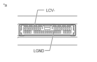
12.CHECK PARKING ASSIST ECU (LCV-, LGND)

NG

REPAIR OR REPLACE HARNESS OR CONNECTOR

12.CHECK PARKING ASSIST ECU (LCV-, LGND)
a.
E330226C76
1.563,0.354 1.333,0.354 1.333,0.354 1.208,0.979 true 1.594,1.781 1.76,1.781 1.76,1.781 1.906,1.135 true 0.115,0.094 0.427,0.25 0.313,0.156 10 false *a 1.188,1.708 1.688,1.865 0.5,0.156 10 false LGND 1.635,0.281 2.135,0.438 0.5,0.156 10 false LCV-
*a Component without harness connected
(Parking Assist ECU)


Disconnect the N151 parking assist ECU connector.


b.

Measure the resistance according to the value(s) in the table below.

Standard Resistance:
Tester Connection Condition Specified Condition
26 (LGND) - Body ground Always Below 1 Ω
13 (LCV-) - Body ground Always Below 1 Ω


Result:
Proceed to
OK
NG


OK

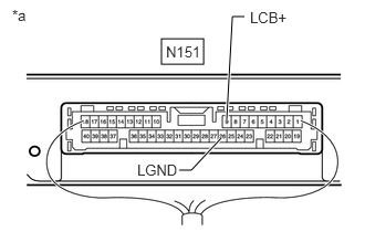
13.CHECK PARKING ASSIST ECU (LCB+, LGND)

NG

13.CHECK PARKING ASSIST ECU (LCB+, LGND)
a.
E348000C30
1.521,0.365 1.917,0.604 0.396,0.24 2.135,1.125 2.188,0.156 2.188,0.156 2.302,0.156 true 2.083,1.302 1.802,1.604 1.802,1.604 1.688,1.604 true 1.563,0.406 1.938,0.563 0.375,0.156 10 false N151 0.115,0.063 0.313,0.24 0.198,0.177 10 false *a 2.354,0.083 2.781,0.24 0.427,0.156 10 false LCB+ 1.292,1.521 1.708,1.677 0.417,0.156 10 false LGND
*a Component with harness connected
(Parking Assist ECU)


Disconnect the outer rear view mirror assembly LH connector.


b.

Measure the resistance according to the value(s) in the table below.

Standard Resistance:
Tester Connection Condition Specified Condition
N151-26 (LGND) - Body ground Always Below 1 Ω


c.

Measure the voltage according to the value(s) in the table below.

Standard Voltage:
Tester Connection Switch Condition Specified Condition
N151-9 (LCB+) - N151-26 (LGND) Engine switch on (IG) 5.5 to 7.05 V
N151-9 (LCB+) - N151-26 (LGND) Engine switch off Below 1 V


Result:
Proceed to
OK
NG


OK

14.CHECK SIDE TELEVISION CAMERA ASSEMBLY LH (LCV+, LGND)

NG

14.CHECK SIDE TELEVISION CAMERA ASSEMBLY LH (LCV+, LGND)
a.

Using an oscilloscope, check the waveform of the side television camera assembly LH.

HINT:

A waterproof connector is used for the side television camera assembly LH. Therefore, inspect the waveform at the parking assist ECU with the connector connected.
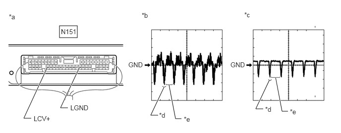

E349540C09
1.25,0.542 1.625,0.792 0.375,0.25 0.656,2.49 0.5,2.49 0.5,2.49 0.99,1.427 true 1.427,2.271 1.271,2.271 1.271,2.271 1.667,1.427 true 3.323,2.427 3.167,2.427 3.167,2.427 3.448,1.833 true 3.813,2.5 3.688,2.5 3.688,2.5 3.552,1.792 true 5.531,2.292 5.375,2.292 5.375,2.292 5.656,1.698 true 6.052,2.344 5.927,2.344 5.927,2.344 5.792,1.635 true 1.281,0.583 1.677,0.76 0.396,0.177 10 false N151 0.188,0.271 0.385,0.448 0.198,0.177 10 false *a 0.708,2.417 1.146,2.594 0.438,0.177 10 false LCV+ 1.479,2.188 1.896,2.354 0.417,0.167 10 false LGND 2.979,0.24 3.177,0.417 0.198,0.177 10 false *b 2.698,1.281 3.052,1.448 0.354,0.167 10 false GND 5.135,0.229 5.333,0.406 0.198,0.177 10 false *c 4.844,1.281 5.198,1.448 0.354,0.167 10 false GND 3.344,2.344 3.542,2.521 0.198,0.177 10 false *d 3.865,2.427 4.063,2.604 0.198,0.177 10 false *e 5.573,2.219 5.771,2.396 0.198,0.177 10 false *d 6.094,2.271 6.292,2.448 0.198,0.177 10 false *e
*a Component with harness connected
(Parking Assist ECU)
*b Waveform 1 (camera lens not covered, displaying an image)
*c Waveform 2 (camera lens covered, blacking out the screen) *d Synchronization Signal
*e Video Waveform - -


HINT:
·

The video waveform changes according to the image sent by the side television camera assembly LH.

·

The video waveform is constantly output when the engine switch is on (ACC).


Measurement Condition
Item Content
Tester Connection N151-36 (LCV+) - N151-26 (LGND)
Tool Setting 200 mV/DIV., 50 μsec./DIV.
Condition Engine switch on (IG), panoramic view monitor switch on

OK:

Waveform is similar to that shown in illustration.


Result:
Proceed to
OK
NG


OK

NG

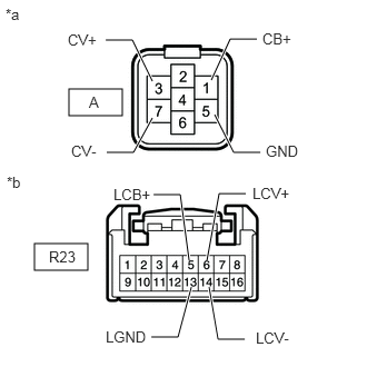
15.INSPECT OUTER REAR VIEW MIRROR ASSEMBLY LH
a.
E407112C08
0.646,0.833 1.146,1.083 0.5,0.25 0.323,2.281 0.823,2.531 0.5,0.25 0.99,0.375 1.24,0.375 1.24,0.375 1.427,0.76 true 2.406,0.365 2.156,0.365 2.156,0.365 1.979,0.75 true 1,1.427 1.25,1.427 1.25,1.427 1.427,1.104 true 2.438,1.427 2.188,1.427 2.188,1.427 2.01,1.073 true 1.438,1.823 1.688,1.823 1.688,1.823 1.771,2.438 true 2.302,1.813 2.052,1.813 2.052,1.813 1.938,2.438 true 2.292,3.177 2.042,3.177 2.042,3.177 1.958,2.688 true 1.417,3.156 1.667,3.156 1.667,3.156 1.792,2.688 true 1.063,1.74 1.677,1.938 0.615,0.198 10 false LCB+ 2.458,0.281 3.073,0.479 0.615,0.198 10 false CB+ 0.635,0.292 1.25,0.49 0.615,0.198 10 false CV+ 0.667,1.333 1.281,1.531 0.615,0.198 10 false CV- 2.49,1.333 3.104,1.531 0.615,0.198 10 false GND 2.365,1.729 2.979,1.927 0.615,0.198 10 false LCV+ 0.99,3.073 1.604,3.271 0.615,0.198 10 false LGND 2.396,3.083 3.01,3.281 0.615,0.198 10 false LCV- 0.833,0.875 1.448,1.073 0.615,0.198 10 false A 0.458,2.323 1.073,2.521 0.615,0.198 10 false R23 0.052,0.052 0.667,0.25 0.615,0.198 10 false *a 0.063,1.625 0.677,1.823 0.615,0.198 10 false *b
*a Front view of wire harness connector
(to Side Television Camera Assembly LH)
*b Front view of wire harness connector
(to Outer Rear View Mirror Assembly LH)


Disconnect the outer rear view mirror assembly LH connector.


b.

Disconnect the side television camera assembly LH connector.


c.

Measure the resistance according to the value(s) in the table below.

Standard Resistance:
Tester Connection Condition Specified Condition
A-1 (CB+) - R23-5 (LCB+) Always Below 1 Ω
A-3 (CV+) - R23-6 (LCV+) Always Below 1 Ω
A-7 (CV-) - R23-14 (LCV-) Always Below 1 Ω
A-5 (GND) - R23-13 (LGND) Always Below 1 Ω
A-1 (CB+) or R23-5 (LCB+) - Body ground Always 10 kΩ or higher
A-3 (CV+) or R23-6 (LCV+) - Body ground Always 10 kΩ or higher
A-7 (CV-) or R23-14 (LCV-) - Body ground Always 10 kΩ or higher
A-5 (GND) or R23-13 (LGND) - Body ground Always 10 kΩ or higher


Result:
Proceed to
OK
NG


OK

16.CHECK SIDE TELEVISION CAMERA ASSEMBLY LH

NG

16.CHECK SIDE TELEVISION CAMERA ASSEMBLY LH
a.

Replace the side television camera assembly LH with a new or normally functioning one.

Click hereAudio / Visual / Telematics>PARK ASSIST / MONITORING>TELEVISION CAMERA (for Side)>REMOVAL


b.

Check if the same malfunction reoccurs when the side monitor screen is displayed.

OK:

Malfunction does not reoccur (returns to normal)


Result:
Proceed to
OK
NG


OK

END (SIDE TELEVISION CAMERA ASSEMBLY LH WAS DEFECTIVE)

NG

17.CHECK HARNESS AND CONNECTOR (PARKING ASSIST ECU - OUTER REAR VIEW MIRROR ASSEMBLY RH)
a.

Disconnect the N151 parking assist ECU connector.


b.

Disconnect the R21 outer rear view mirror assembly RH connector.


c.

Measure the resistance according to the value(s) in the table below.

Standard Resistance:
Tester Connection Condition Specified Condition
N151-6 (RCB+) - R21-5 (RCB+) Always Below 1 Ω
N151-30 (RCV+) - R21-6 (RCV+) Always Below 1 Ω
N151-31 (RCV-) - R21-14 (RCV-) Always Below 1 Ω
N151-23 (RGND) - R21-13 (RGND) Always Below 1 Ω
N151-32 (SGND) - Body ground Always Below 1 Ω
N151-6 (RCB+) or R21-5 (RCB+) - Body ground Always 10 kΩ or higher
N151-30 (RCV+) or R21-6 (RCV+) - Body ground Always 10 kΩ or higher
N151-31 (RCV-) or R21-14 (RCV-) - Body ground Always 10 kΩ or higher
N151-23 (RGND) or R21-13 (RGND) - Body ground Always 10 kΩ or higher


Result:
Proceed to
OK
NG


OK

18.CHECK PARKING ASSIST ECU (RCV-, RGND)

NG

REPAIR OR REPLACE HARNESS OR CONNECTOR

18.CHECK PARKING ASSIST ECU (RCV-, RGND)
a.
E330226C75
2.552,1.875 2.385,1.875 2.385,1.875 2.115,1.156 true 1.083,1.823 1.25,1.823 1.25,1.823 1.563,1.156 true 0.115,0.094 0.427,0.25 0.313,0.156 10 false *a 2.635,1.802 3.135,1.958 0.5,0.156 10 false RGND 0.708,1.74 1.208,1.896 0.5,0.156 10 false RCV-
*a Component without harness connected
(Parking Assist ECU)


Disconnect the N151 parking assist ECU connector.


b.

Measure the resistance according to the value(s) in the table below.

Standard Resistance:
Tester Connection Condition Specified Condition
23 (RGND) - Body ground Always Below 1 Ω
31 (RCV-) - Body ground Always Below 1 Ω


Result:
Proceed to
OK
NG


OK

19.CHECK PARKING ASSIST ECU (RCB+, RGND)

NG

19.CHECK PARKING ASSIST ECU (RCB+, RGND)
a.
E348000C29
1.521,0.365 1.917,0.604 0.396,0.24 2.375,1.135 2.427,0.167 2.427,0.167 2.542,0.167 true 2.333,1.292 2.052,1.594 2.052,1.594 1.938,1.594 true 1.552,0.406 1.938,0.563 0.385,0.156 10 false N151 0.115,0.063 0.313,0.24 0.198,0.177 10 false *a 2.583,0.104 3.01,0.26 0.427,0.156 10 false RCB+ 1.521,1.51 1.938,1.667 0.417,0.156 10 false RGND
*a Component with harness connected
(Parking Assist ECU)


Disconnect the outer rear view mirror assembly RH connector.


b.

Measure the resistance according to the value(s) in the table below.

Standard Resistance:
Tester Connection Condition Specified Condition
N151-23 (RGND) - Body ground Always Below 1 Ω


c.

Measure the voltage according to the value(s) in the table below.

Standard Voltage:
Tester Connection Switch Condition Specified Condition
N151-6 (RCB+) - N151-23 (RGND) Engine switch on (IG) 5.5 to 7.05 V
N151-6 (RCB+) - N151-23 (RGND) Engine switch off Below 1 V


Result:
Proceed to
OK
NG


OK

20.CHECK SIDE TELEVISION CAMERA ASSEMBLY RH (RCV+, RGND)

NG

20.CHECK SIDE TELEVISION CAMERA ASSEMBLY RH (RCV+, RGND)
a.

Using an oscilloscope, check the waveform of the side television camera assembly RH.

HINT:

A waterproof connector is used for the side television camera assembly RH. Therefore, inspect the waveform at the parking assist ECU with the connector connected.
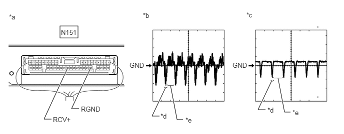

E349540C08
1.25,0.542 1.625,0.792 0.375,0.25 1.073,2.49 0.917,2.49 0.917,2.49 1.406,1.427 true 1.646,2.271 1.49,2.271 1.49,2.271 1.885,1.427 true 3.323,2.427 3.167,2.427 3.167,2.427 3.448,1.833 true 3.813,2.5 3.688,2.5 3.688,2.5 3.552,1.792 true 5.531,2.292 5.375,2.292 5.375,2.292 5.656,1.698 true 6.052,2.344 5.927,2.344 5.927,2.344 5.792,1.635 true 1.271,0.594 1.635,0.76 0.365,0.167 10 false N151 0.188,0.271 0.385,0.448 0.198,0.177 10 false *a 1.104,2.417 1.542,2.594 0.438,0.177 10 false RCV+ 1.688,2.198 2.104,2.365 0.417,0.167 10 false RGND 2.979,0.24 3.177,0.417 0.198,0.177 10 false *b 2.698,1.281 3.052,1.448 0.354,0.167 10 false GND 5.135,0.229 5.333,0.406 0.198,0.177 10 false *c 4.844,1.281 5.198,1.448 0.354,0.167 10 false GND 3.344,2.344 3.542,2.521 0.198,0.177 10 false *d 3.865,2.427 4.063,2.604 0.198,0.177 10 false *e 5.573,2.219 5.771,2.396 0.198,0.177 10 false *d 6.094,2.271 6.292,2.448 0.198,0.177 10 false *e
*a Component with harness connected
(Parking Assist ECU)
*b Waveform 1 (camera lens not covered, displaying an image)
*c Waveform 2 (camera lens covered, blacking out the screen) *d Synchronization Signal
*e Video Waveform - -


HINT:
·

The video waveform changes according to the image sent by the side television camera assembly RH.

·

The video waveform is constantly output when the engine switch is on (ACC).


Measurement Condition
Item Content
Tester Connection N151-30 (RCV+) - N151-23 (RGND)
Tool Setting 200 mV/DIV., 50 μsec./DIV.
Condition Engine switch on (IG), panoramic view monitor switch on

OK:

Waveform is similar to that shown in illustration.


Result:
Proceed to
OK
NG


OK

NG

21.INSPECT OUTER REAR VIEW MIRROR ASSEMBLY RH
a.
E407112C07
0.646,0.833 1.146,1.083 0.5,0.25 0.323,2.281 0.823,2.531 0.5,0.25 0.99,0.375 1.24,0.375 1.24,0.375 1.427,0.76 true 2.406,0.365 2.156,0.365 2.156,0.365 1.979,0.75 true 1,1.427 1.25,1.427 1.25,1.427 1.427,1.104 true 2.438,1.427 2.188,1.427 2.188,1.427 2.01,1.073 true 1.448,1.813 1.698,1.813 1.698,1.813 1.781,2.427 true 2.292,1.781 2.042,1.781 2.042,1.781 1.927,2.406 true 2.271,3.167 2.021,3.167 2.021,3.167 1.938,2.677 true 1.396,3.135 1.646,3.135 1.646,3.135 1.771,2.667 true 1.031,1.729 1.646,1.927 0.615,0.198 10 false RCB+ 2.458,0.292 3.073,0.49 0.615,0.198 10 false CB+ 0.625,0.281 1.24,0.479 0.615,0.198 10 false CV+ 0.604,1.333 1.219,1.531 0.615,0.198 10 false CV- 2.49,1.333 3.104,1.531 0.615,0.198 10 false GND 2.396,1.698 3.01,1.896 0.615,0.198 10 false RCV+ 0.948,3.073 1.563,3.271 0.615,0.198 10 false RGND 2.365,3.063 2.979,3.26 0.615,0.198 10 false RCV- 0.833,0.875 1.448,1.073 0.615,0.198 10 false B 0.458,2.323 1.073,2.521 0.615,0.198 10 false R21 0.052,0.052 0.667,0.25 0.615,0.198 10 false *a 0.063,1.625 0.677,1.823 0.615,0.198 10 false *b
*a Front view of wire harness connector
(to Side Television Camera Assembly RH)
*b Front view of wire harness connector
(to Outer Rear View Mirror Assembly RH)


Disconnect the side television camera assembly RH connector.


b.

Disconnect the outer rear view mirror assembly RH connector.


c.

Measure the resistance according to the value(s) in the table below.

Standard Resistance:
Tester Connection Condition Specified Condition
B-1 (CB+) - R21-5 (RCB+) Always Below 1 Ω
B-3 (CV+) - R21-6 (RCV+) Always Below 1 Ω
B-7 (CV-) - R21-14 (RCV-) Always Below 1 Ω
B-5 (GND) - R21-13 (RGND) Always Below 1 Ω
B-1 (CB+) or R21-5 (RCB+) - Body ground Always 10 kΩ or higher
B-3 (CV+) or R21-6 (RCV+) - Body ground Always 10 kΩ or higher
B-7 (CV-) or R21-14 (RCV-) - Body ground Always 10 kΩ or higher
B-5 (GND) or R21-13 (RGND) - Body ground Always 10 kΩ or higher


Result:
Proceed to
OK
NG


OK

22.CHECK SIDE TELEVISION CAMERA ASSEMBLY RH

NG

22.CHECK SIDE TELEVISION CAMERA ASSEMBLY RH
a.

Replace the side television camera assembly RH with a new or normally functioning one.

Click hereAudio / Visual / Telematics>PARK ASSIST / MONITORING>TELEVISION CAMERA (for Side)>REMOVAL


b.

Check if the same malfunction reoccurs when the side monitor screen is displayed.

OK:

Malfunction does not reoccur (returns to normal)


Result:
Proceed to
OK
NG


OK

END (SIDE TELEVISION CAMERA ASSEMBLY RH WAS DEFECTIVE)

NG

23.CHECK HARNESS AND CONNECTOR (PARKING ASSIST ECU - RADIO AND DISPLAY RECEIVER ASSEMBLY)
a.

Disconnect the N151 parking assist ECU connector.


b.

Disconnect the O7 radio and display receiver assembly connector.


c.

Measure the resistance according to the value(s) in the table below.

Standard Resistance:
Tester Connection Condition Specified Condition
N151-27 (NS+) - O7-28 (V+) Always Below 1 Ω
N151-28 (NS-) - O7-29 (V-) Always Below 1 Ω
N151-37 (RSW+) - O7-18 (CSW+) Always Below 1 Ω
N151-29 (NSG) - Body ground Always Below 1 Ω
N151-27 (NS+) or O7-28 (V+) - Body ground Always 10 kΩ or higher
N151-28 (NS-) or O7-29 (V-) - Body ground Always 10 kΩ or higher
N151-37 (RSW+) or O7-18 (CSW+) - Body ground Always 10 kΩ or higher


Result:
Proceed to
OK
NG


OK

24.CHECK PARKING ASSIST ECU

NG

REPAIR OR REPLACE HARNESS OR CONNECTOR

24.CHECK PARKING ASSIST ECU
a.

Disconnect the O7 radio and display receiver assembly connector.


b.

Using an oscilloscope, check the waveform of the parking assist ECU.
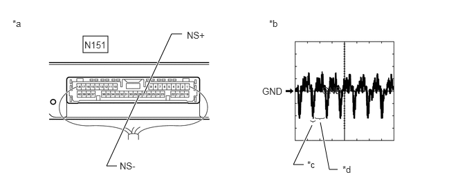
E419401C01
1.25,0.542 1.625,0.792 0.375,0.25 1.76,2.5 1.604,2.5 1.604,2.5 2.094,1.438 true 2.74,0.51 2.583,0.51 2.583,0.51 2.167,1.406 true 4.573,2.479 4.417,2.479 4.417,2.479 4.698,1.885 true 5.083,2.552 4.958,2.552 4.958,2.552 4.823,1.844 true 1.271,0.594 1.635,0.76 0.365,0.167 10 false N151 0.188,0.271 0.385,0.448 0.198,0.177 10 false *a 2.813,0.448 3.25,0.625 0.438,0.177 10 false NS+ 1.802,2.417 2.219,2.583 0.417,0.167 10 false NS- 4.052,0.271 4.25,0.448 0.198,0.177 10 false *b 3.948,1.292 4.302,1.458 0.354,0.167 10 false GND 4.844,1.281 5.198,1.448 0.354,0.167 10 false GND 4.625,2.396 4.823,2.573 0.198,0.177 10 false *c 5.156,2.469 5.354,2.646 0.198,0.177 10 false *d
*a Component with harness connected
(Parking Assist ECU)
*b Waveform (camera lens not covered, displaying an image)
*c Synchronization Signal *d Video Waveform


HINT:

The video waveform changes according to the image sent by the parking assist ECU.


Measurement Condition
Item Content
Tester Connection N151-27 (NS+) - N151-28 (NS-)
Tool Setting 200 mV/DIV., 50 μsec./DIV.
Condition Engine switch on (IG), panoramic view monitor switch on, camera lens not covered, displaying image

OK:

Waveform is similar to that shown in illustration.


Result:
Proceed to
OK
NG


OK

NG