HEATING / AIR CONDITIONING AIR CONDITIONING SYSTEM(for Automatic Air Conditioning System) B1417 Evaporator Temperature Circuit
DESCRIPTION
The No. 2 cooler thermistor is installed on the evaporator in the rear cooling unit to detect the temperature of the air that has passed through the evaporator and is used to control the air conditioning. It sends signals to the air conditioning amplifier assembly. The resistance of the No. 2 cooler thermistor changes in accordance with the cooled air temperature that has passed through the evaporator. As the temperature decreases, the resistance increases. As the temperature increases, the resistance decreases.
The air conditioning amplifier assembly applies voltage (5 V) to the No. 2 cooler thermistor and reads voltage changes as the resistance of the No. 2 cooler thermistor changes. This sensor is used for frost prevention.
| DTC No. | Detection Item | DTC Detection Condition | Trouble Area | Memory |
|---|---|---|---|---|
| B1417 | Evaporator Temperature Circuit | ·
Diagnosis condition: None ·
Malfunction status: Open or short in evaporator temperature sensor circuit ·
Detection time: None (Present malfunction), continuously for 4 seconds or more (Past malfunction) |
·
No. 2 cooler thermistor (for Rear Automatic Cooler) ·
No. 2 air conditioning harness assembly (for Rear Automatic Air Conditioning) ·
Harness or connector ·
Air conditioning amplifier assembly |
Memorized |
WIRING DIAGRAM
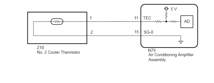
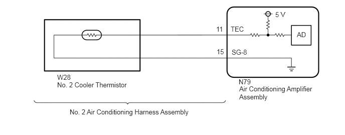
PROCEDURE
Connect the GTS to the DLC3.
Turn the engine switch on (IG).
Turn the GTS on.
Enter the following menus: Body Electrical / Air Conditioner / Data List.
Check the value(s) by referring to the table below.
- Body Electrical > Air Conditioner > Data List
-
Tester Display Measurement Item Range Normal Condition Diagnostic Note Evap Temp Sensor (Rear) No. 2 cooler thermistor Min.: -29.70°C (-21.46°F)
Max.: 59.55°C (139.19°F)Actual evaporator temperature displayed No. 2 cooler thermistor system malfunction:
·When open circuit: -29.70°C (-21.46°F)
·When short circuit: 59.55°C (139.19°F)
- Body Electrical > Air Conditioner > Data List
-
Tester Display Evap Temp Sensor (Rear) - 50003 121 55
- OK:
The display is as specified in the normal condition column.
- Result:
Result Proceed to OK A NG (for Rear Automatic Cooler) B NG (for Rear Automatic Air Conditioning) C
A
B
C
Inspect the No. 2 cooler thermistor.
- Result:
Proceed to OK NG
OK
NG
Disconnect the Z10 No. 2 cooler thermistor connector.
Disconnect the N79 air conditioning amplifier assembly connector.
Measure the resistance according to the value(s) in the table below.
- Standard Resistance:
Tester Connection Condition Specified Condition Z10-1 - N79-11 (TEC) Always Below 1 Ω Z10-2 - N79-15 (SG-8) Always Below 1 Ω Z10-1 or N79-11 (TEC) - Other terminals and body ground Always 10 kΩ or higher Z10-2 or N79-15 (SG-8) - Other terminals and body ground Always 10 kΩ or higher
- Result:
Proceed to OK NG
OK
NG
Remove the No. 2 air conditioning harness assembly.
Inspect the No. 2 air conditioning harness assembly.
- Result:
Proceed to OK NG
OK
NG