BRAKE CONTROL / DYNAMIC CONTROL SYSTEMS ELECTRONICALLY CONTROLLED BRAKE SYSTEM(w/ VSC OFF Switch) AUTO LSD Indicator Light Remains ON
DESCRIPTION
The AUTO LSD is a system. When the VSC OFF switch is pushed on, the AUTO LSD function is available and the AUTO LSD indicator light illuminates.
- HINT:
-
The AUTO LSD does not operate even if the VSC OFF switch (telltale light assembly) is pressed under the following conditions:
- ·
The TRC or VSC system is faulty.
·The temperature inside the brake actuator assembly increases and the AUTO LSD operation is suspended.
WIRING DIAGRAM
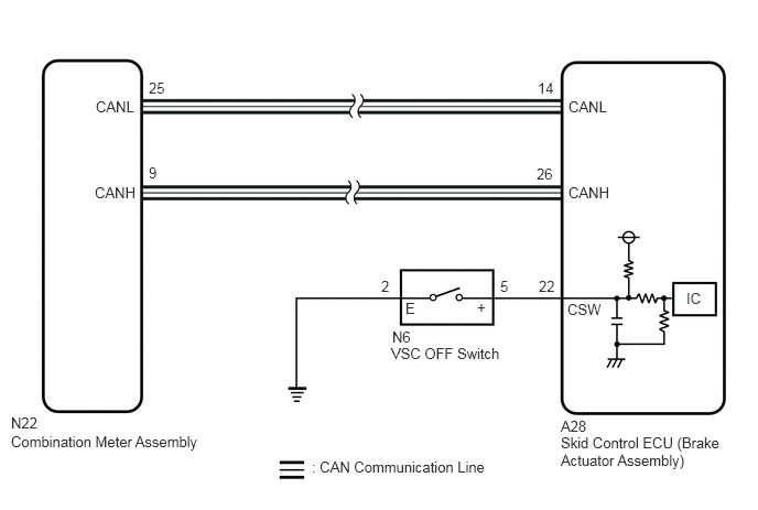
CAUTION / NOTICE / HINT
- NOTICE:
-
After replacing the skid control ECU (brake actuator assembly), perform acceleration sensor zero point calibration and store system information memorization.
PROCEDURE
Inspect the VSC OFF switch.
- Result:
Proceed to OK NG
OK
NG
Make sure that there is no looseness at the locking part and the connecting part of the connector.
- OK:
The connector is securely connected.
Disconnect the A28 skid control ECU (brake actuator assembly) connector.
Disconnect the N6 VSC OFF switch connector.
Check both the connector case and the terminals for deformation and corrosion.
- OK:
No deformation or corrosion.
Measure the resistance according to the value(s) in the table below.
- Standard Resistance:
Tester Connection Condition Specified Condition N6-5 (+) or A28-22 (CSW) - Body ground Always 10 kΩ or higher
- Result:
Proceed to OK NG
OK
NG
Connect the GTS to the DLC3.
Turn the ignition switch to ON.
Enter the following menus: Body Electrical / Combination Meter / Active Test.
Perform the Active Test of the combination meter assembly using the GTS.
- Body Electrical > Combination Meter > Active Test
-
Tester Display Auto LSD Indicator - 50004 409 102
Check the combination meter assembly.
- OK:
The Auto LSD light turns on or off in accordance with the GTS operation.
- Result:
Proceed to OK NG
OK
NG