HEATING / AIR CONDITIONING AIR CONDITIONING SYSTEM(for Automatic Air Conditioning System) Air Conditioning Compressor Magnetic Clutch Circuit
DESCRIPTION
The air conditioning amplifier assembly outputs the magnet clutch on request signal to the ECM. The ECM sends a magnet clutch on permission signal to the air conditioning amplifier assembly. The air conditioning amplifier assembly turns the magnet clutch on based on this signal.
| Malfunction Status | Factor |
|---|---|
| Refrigerant pressure does not decrease when A/C switch is off. | Compressor with magnet clutch assembly circuit malfunction |
WIRING DIAGRAM
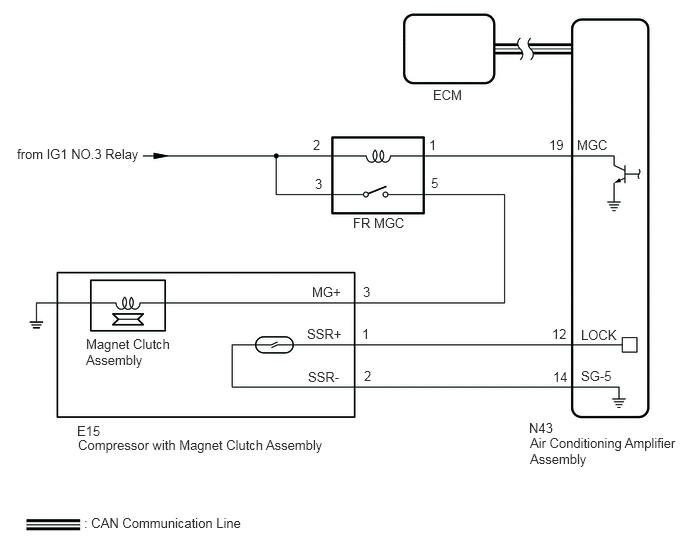
CAUTION / NOTICE / HINT
- NOTICE:
- ·
Inspect the relays for circuits related to this system before performing the following procedure.
·If DTC B1422 is output at the same time, troubleshoot for DTC B1422 first.
PROCEDURE
Using the GTS, check if the CAN communication system is functioning normally.
- OK:
CAN communication system DTCs are not output.
- Result:
Proceed to OK NG
OK
NG
Remove the magnet-clutch relay (FR MGC) from the No. 1 engine room relay block assembly.
Inspect the magnet-clutch relay (FR MGC).
- Result:
Proceed to OK NG
OK
NG
Remove the magnet clutch assembly.
Inspect the magnet clutch assembly.
- Result:
Proceed to OK NG
OK
NG
Remove the magnet-clutch relay (FR MGC) from the No. 1 engine room relay block assembly.
Disconnect the E15 compressor assembly with magnet clutch connector.
Measure the resistance according to the value(s) in the table below.
- Standard Resistance:
Tester Connection Condition Specified Condition Terminal 5 - E15-3 (MG+) Always Below 1 Ω Terminal 5 or E15-3 (MG+) - Other terminals and body ground Always 10 kΩ or higher
Measure the voltage according to the value(s) in the table below.
- Standard Voltage:
Tester Connection Switch Condition Specified Condition Terminal 2 - Body ground Ignition switch off Below 1 V Terminal 2 - Body ground Ignition switch ON 11 to 14 V Terminal 3 - Body ground Ignition switch off Below 1 V Terminal 3 - Body ground Ignition switch ON 11 to 14 V
- Result:
Proceed to OK NG
OK
NG
Remove the magnet-clutch relay (FR MGC) from the No. 1 engine room relay block assembly.
Disconnect the N43 air conditioning amplifier assembly connector.
Measure the resistance according to the value(s) in the table below.
- Standard Resistance:
Tester Connection Condition Specified Condition Terminal 1 - N43-19 (MGC) Always Below 1 Ω Terminal 1 or N43-19 (MGC) - Other terminals and body ground Always 10 kΩ or higher
- Result:
Proceed to OK NG
OK
NG

| *a | Component with harness connected
(Air Conditioning Amplifier Assembly) |
Remove the air conditioning amplifier assembly with its connectors still connected.
Measure the voltage according to the value(s) in the table below.
- Standard Voltage:
Tester Connection Condition Specified Condition N43-19 (MGC) - Body ground ·Engine idling
·Blower switch: On (LO level)
·A/C switch: On (magnet clutch on)
Below 1 V N43-19 (MGC) - Body ground ·Engine idling
·Blower switch: On (LO level)
·A/C switch: Off or on (magnet clutch off)
11 to 14 V
- Result:
Proceed to OK NG
OK
NG