7GR-FKS FUEL FUEL TANK INSTALLATION
PROCEDURE

 77213E
1.INSTALL FUEL TANK TO FILLER PIPE HOSE
77213E
1.INSTALL FUEL TANK TO FILLER PIPE HOSE

| *1 | Fuel Tank Assembly Side Mark |
| *2 | Fuel Tank to Filler Pipe Hose Side Mark |
Install the fuel tank to filler pipe hose to the fuel tank assembly and tighten the hose clamp.
- NOTICE:
-
Align the fuel tank assembly side mark with the hose side mark.
77697A
2.INSTALL NO. 2 FUEL TANK HEAT INSULATOR
Install the No. 2 fuel tank heat insulator with the 2 nuts.
- Torque:
- 5.0 N*m (51 kgf*cm, 44 in.*lbf)
77697
3.INSTALL NO. 1 FUEL TANK HEAT INSULATOR
Install the No. 1 fuel tank heat insulator with the 2 nuts.
- Torque:
- 5.0 N*m (51 kgf*cm, 44 in.*lbf)
77754B
4.INSTALL CHARCOAL CANISTER OUTLET HOSE
Attach the clamp and install the charcoal canister outlet hose to the fuel tank assembly.
77209C
5.INSTALL FUEL TANK MAIN TUBE SUB-ASSEMBLY
Attach the clamp and install the fuel main tube sub-assembly to the fuel tank assembly.
77027
6.INSTALL NO. 2 FUEL EVAPORATION TUBE SUB-ASSEMBLY
Attach the clamp and install the No. 2 fuel evaporation tube sub-assembly to the fuel tank assembly.
7.INSTALL FUEL TANK CUSHION
Install the 2 No. 1 fuel tank cushions and No. 2 fuel tank cushion to the fuel tank assembly.
77100
8.INSTALL FUEL TANK ASSEMBLY
- CAUTION:
-
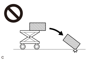
-
The fuel tank assembly is very heavy. Be sure to follow the procedure described in the repair manual, or the fuel tank assembly may fall off the engine lifter.
Set the fuel tank assembly on an engine lifter.
- NOTICE:
-
Using height adjustment attachments and plate lift attachments, keep the fuel tank assembly horizontal.
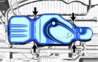
Using the engine lifter, slowly raise the fuel tank assembly, and install the fuel tank assembly and 2 fuel tank band sub-assemblies with the 4 bolts.
- Torque:
- 45 N*m (459 kgf*cm, 33 ft.*lbf)
- NOTICE:
- ·
Be careful not to drop the fuel tank assembly.
·When installing the fuel tank assembly, tilt it slightly to prevent it from interfering with the surrounding parts.
77287A
9.CONNECT FUEL HOSE
Slide the clip and connect the fuel hose to the charcoal canister outlet hose.
77269A
10.CONNECT FUEL TANK BREATHER HOSE
Slide the clip and connect the fuel tank breather hose to the fuel tank breather tube.
77027
11.CONNECT NO. 2 FUEL EVAPORATION TUBE SUB-ASSEMBLY
Slide the clip and connect the No. 2 fuel evaporation tube sub-assembly to the fuel tank to canister tube.
77209C
12.CONNECT FUEL TANK MAIN TUBE SUB-ASSEMBLY
Connect the 2 fuel tank main tube sub-assemblies to the fuel pipe.
77213E
13.CONNECT FUEL TANK TO FILLER PIPE HOSE
Connect the fuel tank to filler pipe hose and tighten the hose clamp.
77276
14.INSTALL FUEL HOSE PROTECTOR
Attach the 2 clamps and install the fuel hose protector.
77697B
15.INSTALL NO. 3 FUEL TANK HEAT INSULATOR
Install the No. 2 fuel tank heat insulator with the 2 bolts and nut.
- Torque:
- 8.0 N*m (82 kgf*cm, 71 in.*lbf)
16.ADD FUEL
77020A
17.INSTALL FUEL SUCTION WITH PUMP AND GAUGE TUBE ASSEMBLY
18.CONNECT CABLE TO NEGATIVE BATTERY TERMINAL
19. INITIALIZATION AFTER RECONNECTING BATTERY TERMINAL
- HINT:
-
When disconnecting and reconnecting the battery, there is an automatic learning function that completes learning when the respective system is used.