7GR-FKS FUEL FUEL PUMP(for High Pressure) INSTALLATION
CAUTION / NOTICE / HINT
- HINT:
-
Perform "Inspection After Repairs" after replacing the fuel injector assembly.
PROCEDURE

 23100X
1.TEMPORARILY INSTALL FUEL (ENGINE ROOM SIDE) PUMP ASSEMBLY
23100X
1.TEMPORARILY INSTALL FUEL (ENGINE ROOM SIDE) PUMP ASSEMBLY
- HINT:
-
Perform "Inspection After Repairs" after replacing the fuel injector assembly.
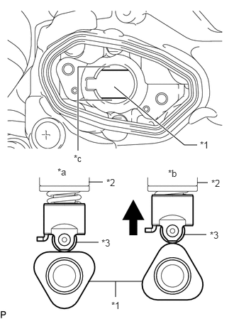
| *1 | Camshaft |
| *2 | Fuel Pump Assembly |
| *3 | Fuel Pump Lifter Assembly |
| *a | Correct |
| *b | Incorrect |
| *c | Oil Collection Area |
Turn the crankshaft pulley until the flat of the camshaft faces the fuel pump lifter assembly.
- HINT:
-
By performing the above procedure, the protruding part of the camshaft does not push up the drive face of the fuel pump when installing the fuel pump, thus making installation of the fuel pump and No. 1 fuel pipe sub-assembly easier.
Fill the fuel pump lifter housing oil collection areas with 30 cc (1.8 cu. in.) of engine oil from the fuel pump assembly hole of the cylinder head cover sub-assembly.
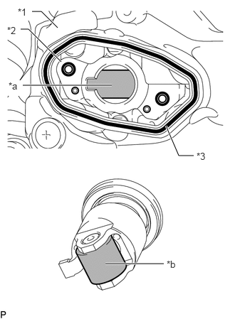
| *1 | Cylinder Head Cover Sub-assembly |
| *2 | Fuel Pump Lifter Housing |
| *3 | Fuel Pump Spacer Gasket |
| *a | Pump Drive Cam (Engine Oil Application Area) |
| *b | Fuel Pump Lifter Assembly (Engine Oil Application Area) |
Apply engine oil to the pump drive cam and fuel pump lifter assembly.
Install a new fuel pump spacer gasket to the cylinder head cover sub-assembly.
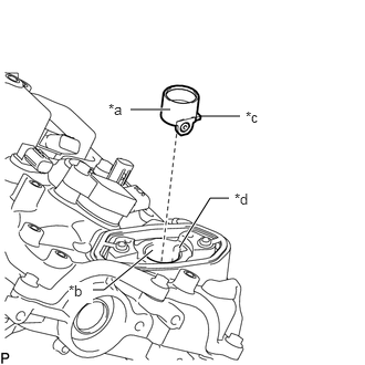
| *a | Fuel Pump Lifter Assembly (Engine Oil Application Area) |
| *b | Fuel Pump Lifter Housing (Engine Oil Application Area) |
| *c | Stopper Key |
| *d | Key Groove |
Apply engine oil to the inside of the fuel pump lifter housing and the outside of the fuel pump lifter assembly.
Set the fuel pump lifter assembly on the fuel pump lifter housing as shown in the illustration.
- HINT:
-
Align the stopper key of the fuel pump lifter assembly with the key groove of the fuel pump lifter housing.
Apply engine oil to a new O-ring and install it to the fuel pump assembly.
- NOTICE:
-
Do not damage the O-ring.
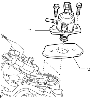
| *1 | Fuel Pump Assembly |
| *2 | Fuel Pump Lifter Guide |
Set the fuel pump lifter guide and fuel pump assembly on the cylinder head cover sub-assembly as shown in the illustration.
Temporarily install the fuel pump assembly with the 2 bolts, leaving some allowance for left and right movement.
23801P
2.TEMPORARILY INSTALL NO. 1 FUEL PIPE SUB-ASSEMBLY
Temporarily install the union nuts on the fuel delivery pipe side of the No. 1 fuel pipe sub-assembly until they are completely tightened.
- NOTICE:
-
Do not damage the seals of the union nuts of the No. 1 fuel pipe sub-assembly when installing.
Temporarily install the union nuts on the fuel pump assembly side of the No. 1 fuel pipe sub-assembly until they are completely tightened.
- NOTICE:
-
Do not damage the seals of the union nuts of the No. 1 fuel pipe sub-assembly when installing.
23100X
3.INSTALL FUEL (ENGINE ROOM SIDE) PUMP ASSEMBLY
- HINT:
-
Perform "Inspection After Repair" after replacing the fuel pump assembly.
Tighten the 2 bolts.
- Torque:
- 26 N*m (265 kgf*cm, 19 ft.*lbf)
23801P
4.INSTALL NO. 1 FUEL PIPE SUB-ASSEMBLY
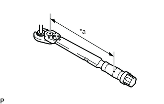
| *a | Torque Wrench Fulcrum Length |
Using a 17 mm union nut wrench, tighten the union nut on the fuel pump assembly side of the No. 1 fuel pipe sub-assembly.
- Torque:
- Specified tightening torque : 35 N*m (357 kgf*cm, 26 ft.*lbf)
- NOTICE:
-
Do not adjust the torque in the loosening direction.
- HINT:
- ·
Calculate the torque wrench reading when changing the fulcrum length of the torque wrench.
·When using a 17 mm union nut wrench (fulcrum length of 30 mm (1.18 in.)) + torque wrench (fulcrum length of 180 mm (7.09 in.)): 30 N*m (306 kgf*cm, 22 ft.*lbf)
Using a 17 mm union nut wrench, tighten the union nut on the fuel delivery pipe RH side of the No. 1 fuel pipe sub-assembly.
- Torque:
- Specified tightening torque : 35 N*m (357 kgf*cm, 26 ft.*lbf)
- NOTICE:
-
Do not adjust the torque in the loosening direction.
- HINT:
- ·
Calculate the torque wrench reading when changing the fulcrum length of the torque wrench.
·When using a 17 mm union nut wrench (fulcrum length of 30 mm (1.18 in.)) + torque wrench (fulcrum length of 180 mm (7.09 in.)): 30 N*m (306 kgf*cm, 22 ft.*lbf)
23903
5.INSTALL NO. 3 FUEL TUBE SUB-ASSEMBLY
Install the No. 3 fuel tube sub-assembly with the bolt.
- Torque:
- 10 N*m (102 kgf*cm, 7 ft.*lbf)
Connect the 2 fuel tube sub-assemblies.
for LHD:
Attach the 2 clamps and connect the wire harness.
Install the bolt and connect the wire harness.
- Torque:
- 13 N*m (133 kgf*cm, 10 ft.*lbf)
Attach the clamp.
Attach the 2 clamps and connect the wire harness.
Install the bolt.
- Torque:
- 13 N*m (133 kgf*cm, 10 ft.*lbf)
17111
6.INSTALL INTAKE MANIFOLD
7.CONNECT CABLE TO NEGATIVE BATTERY TERMINAL
8. INITIALIZATION AFTER RECONNECTING BATTERY TERMINAL
- HINT:
-
When disconnecting and reconnecting the battery, there is an automatic learning function that completes learning when the respective system is used.
9.INSPECT FOR FUEL LEAK