7GR-FKS INTAKE / EXHAUST INTAKE MANIFOLD INSTALLATION
PROCEDURE

 17111
1.INSTALL INTAKE MANIFOLD
17111
1.INSTALL INTAKE MANIFOLD
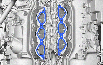
Set 2 new No. 1 intake manifold to head gaskets on each cylinder head as shown in the illustration.
- NOTICE:
- ·
Align the port holes of the gasket and cylinder head sub-assembly and cylinder head LH.
·Be careful of the installation direction.
Set the intake manifold on the cylinder head sub-assembly and cylinder head LH.
Install and uniformly tighten the 4 bolts and 4 nuts.
- Torque:
- 21 N*m (214 kgf*cm, 15 ft.*lbf)
23800
2.INSTALL FUEL DELIVERY WITH SENSOR PIPE ASSEMBLY
17190
3.INSTALL INTAKE AIR SURGE TANK ASSEMBLY
- NOTICE:
-
Do not apply oil to the bolts and nuts as listed below:
Oil Application Prohibited Bolt and Nut Bolt and Nut for Intake Air Surge Tank Assembly and Intake Manifold
Install a new air surge tank to intake manifold gasket to the intake air surge tank assembly.
Set the intake air surge tank assembly on the intake manifold.
Install and uniformly tighten the 5 bolts and 2 nuts.
- Torque:
- 21 N*m (214 kgf*cm, 15 ft.*lbf)
Connect the PCV hose to the intake air surge tank assembly, and slide the clamp to secure the hose.
Connect the intake air control valve actuator connector to the intake air control valve actuator.
Install the 2 bolts to connect the engine wire to the intake air surge tank assembly.
- Torque:
- 13 N*m (133 kgf*cm, 10 ft.*lbf)
Attach the clamp to connect the No. 1 fuel pipe sub-assembly and No. 2 fuel pipe sub-assembly.
Connect the fuel vapor feed hose to the purge VSV, and slide the clamp to secure the hose.
Attach the clamp to the intake air surge tank assembly.
Attach the 2 wire harness clamps and connect the purge VSV connector to the purge VSV.
Connect the No. 4 water by-pass hose and No. 5 water by-pass hose to the throttle body with motor assembly, and slide the 2 clamps to secure the hoses.
Connect the throttle body with motor assembly connector.
4.CONNECT HEATER WATER HOSE ASSEMBLY
22267A
5.INSTALL THROTTLE BODY BRACKET
Install the throttle body bracket to the timing chain or belt cover sub-assembly and intake air surge tank assembly with the 2 bolts.
- Torque:
- 21 N*m (214 kgf*cm, 15 ft.*lbf)
w/ Secondary Air Injection System:
Install the air tube assembly to the throttle body bracket with the bolt.
- Torque:
- 10 N*m (102 kgf*cm, 7 ft.*lbf)
17125
6.INSTALL NO. 1 SURGE TANK STAY
Install the No. 1 surge tank stay to the cylinder head LH and intake air surge tank assembly with the 2 bolts.
- Torque:
- 21 N*m (214 kgf*cm, 15 ft.*lbf)
Attach the 2 wire harness clamps and install the wire harness with the bolt.
- Torque:
- 13 N*m (133 kgf*cm, 10 ft.*lbf)
17126
7.INSTALL NO. 2 SURGE TANK STAY
Install the No. 2 surge tank stay to the cylinder head LH and intake air surge tank assembly with the 2 bolts.
- Torque:
- 21 N*m (214 kgf*cm, 15 ft.*lbf)
for Manual Transmission:
Install the flexible hose bracket to intake air surge tank assembly with the bolt.
- Torque:
- 20 N*m (204 kgf*cm, 15 ft.*lbf)
w/o Secondary Air Injection System:
Install the clutch pipe clamp to the No. 2 surge tank stay and clutch hose bracket with the bolt and nut.
- Torque:
- 13.5 N*m (138 kgf*cm, 10 ft.*lbf)
w/ Secondary Air Injection System:
Install the clutch pipe clamp to the No. 2 surge tank stay with the bolt.
- Torque:
- 13.5 N*m (138 kgf*cm, 10 ft.*lbf)
55701J
8.INSTALL COWL TOP OUTER PANEL SUB-ASSEMBLY
85110
9.INSTALL WINDSHIELD WIPER MOTOR ASSEMBLY
17881
10.INSTALL NO. 1 AIR CLEANER HOSE

| *a | Upper |
| *b | Front Side |
| *c | Stopper |
Install the No. 1 air cleaner hose with the 2 hose clamps.
- Torque:
- 4.0 N*m (41 kgf*cm, 35 in.*lbf)
- HINT:
-
Make sure the hose clamp is oriented as shown in the illustration.
Connect the No. 2 PCV hose to the No. 1 air cleaner hose, and slide the clamp to secure the hose.
11209
11.INSTALL V-BANK COVER SUB-ASSEMBLY (w/ Cover)
12.CONNECT CABLE TO NEGATIVE BATTERY TERMINAL
13. INITIALIZATION AFTER RECONNECTING BATTERY TERMINAL
- HINT:
-
When disconnecting and reconnecting the battery, there is an automatic learning function that completes learning when the respective system is used.
14.BLEED CLUTCH PIPE LINE (for Manual Transmission)
31301
15.INSPECT AND ADJUST CLUTCH PEDAL SUB-ASSEMBLY (for Manual Transmission)
16.ADD ENGINE COOLANT
17.INSPECT FOR COOLANT LEAK
18.INSPECT FOR FUEL LEAK
51405A
19.INSTALL NO. 1 ENGINE UNDER COVER SUB-ASSEMBLY
52618
20.INSTALL LOWER FRONT BUMPER ABSORBER
51406A
21.INSTALL NO. 2 ENGINE UNDER COVER SUB-ASSEMBLY (w/ No. 2 Engine Under Cover Sub-assembly)