7GR-FKS FUEL FUEL INJECTOR(for Direct Injection) INSTALLATION
CAUTION / NOTICE / HINT
- HINT:
-
Perform "Inspection After Repairs" after replacing the direct fuel injector assembly.
PROCEDURE

 23255A
1.INSTALL FUEL INJECTOR SEAL
23255A
1.INSTALL FUEL INJECTOR SEAL
- HINT:
-
Perform "Inspection After Repairs" after replacing the direct fuel injector assembly.
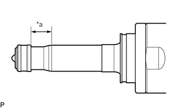
| *a | Clean Area |
Apply engine conditioner to the area shown in the illustration. Using a piece of cloth, clean carbon deposits from the direct fuel injector assembly and its grooves.
- NOTICE:
- ·
Do not clean the tip of the direct fuel injector assembly.
·Do not use a wire brush to clean the direct fuel injector assembly.
·If a direct fuel injector assembly is dropped or the tip of the direct fuel injector assembly is struck, replace it with a new one.
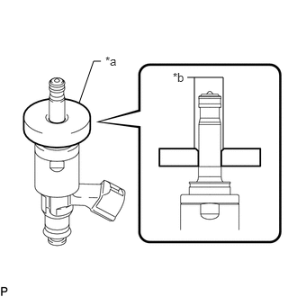
| *a | SST (Guide) |
| *b | Tapered Inner Portion |
Apply engine oil to the direct fuel injector assembly contact surface of SST (guide), then attach SST (guide) to the direct fuel injector assembly with the chamfer facing the tip of the direct fuel injector assembly as shown in the illustration.
- SST
- 09260-39021 (09261-03020)
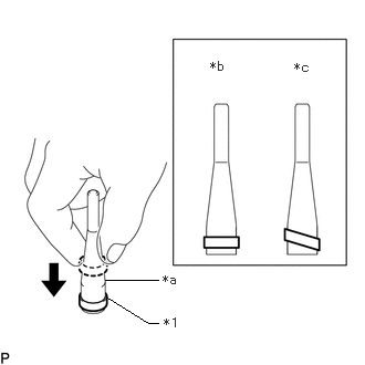
| *1 | Fuel Injector Seal |
| *a | SST (Holder) |
| *b | Correct |
| *c | Incorrect |
Install a new fuel injector seal to SST (holder).
- SST
- 09260-39021 (09261-03011)
- NOTICE:
-
Be careful not to install the fuel injector seal to SST (holder) at an angle. Doing so will stretch the fuel injector seal and correcting this problem is very complicated.
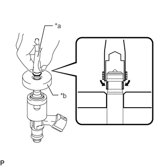
| *a | SST (Holder) |
| *b | SST (Guide) |
Install SST (holder with injector seal) to the tip of the direct fuel injector assembly. Slide the fuel injector seal downward into the direct fuel injector assembly groove (injector connector side) with your fingers as shown in the illustration.
- SST
- 09260-39021 (09261-03011, 09261-03020)
- HINT:
-
Check that the fuel injector seal is seated in the direct fuel injector assembly groove as shown in the illustration.
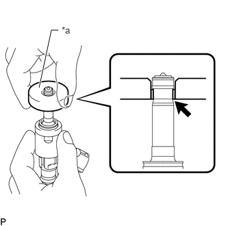
| *a | SST (Guide) |
Slowly slide SST (guide) toward the tip of the direct fuel injector assembly. When the direct fuel injector assembly contact surface of SST (guide) aligns with the fuel injector seal as shown in the illustration, hold the position for 5 seconds or more to fully seat the fuel injector seal into the direct fuel injector assembly groove.
- SST
- 09260-39021 (09261-03020)
- NOTICE:
-
Make sure the fuel injector seal is not pinched between SST (guide) and the edge of the direct fuel injector assembly groove. Replace the fuel injector seal if it becomes damaged.
- HINT:
- ·
Set SST (guide) so that its bottom surface is flush with the fuel injector seal.
·If it is difficult to slide SST (guide) upward, slowly wiggle it from side to side while sliding it up the direct fuel injector assembly little by little.
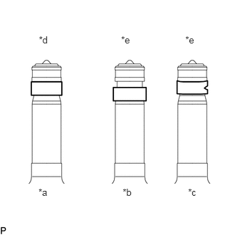
| *a | Normal |
| *b | Protruding |
| *c | Deformed |
| *d | Correct |
| *e | Incorrect |
After installing the fuel injector seals, check that they are not scratched, deformed or protruding from the direct fuel injector assembly groove.
- NOTICE:
-
If a fuel injector seal is scratched, deformed or protruding from the groove, replace it with a new one.
- HINT:
-
Use the same procedure to install the other fuel injector seals.
23250E
2.INSTALL DIRECT FUEL INJECTOR ASSEMBLY
- HINT:
-
Perform "Inspection After Repair" after replacing a direct fuel injector assembly.
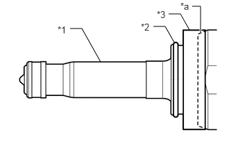
| *1 | Direct Fuel Injector Assembly |
| *2 | C-ring |
| *3 | Injector Vibration Insulator |
| *a | Taper |
Install a new injector vibration insulator and a new C-ring to each direct fuel injector assembly.
- NOTICE:
- ·
Install the taper of the injector vibration insulator by aligning it with the taper of the direct fuel injector assembly.
·Check that the C-ring is securely seated in the groove of the direct fuel injector assembly.
Install a new O-ring and a new No. 1 fuel injector back-up ring to each direct fuel injector assembly as shown in the illustration.
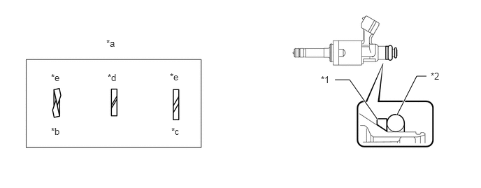
| *1 | No. 1 Fuel Injector Back-up Ring | *2 | O-ring |
| *a | No. 1 Fuel Injector Back-up Ring Opening | *b | Overlapped |
| *c | Stretched | *d | Correct |
| *e | Incorrect | - | - |
- NOTICE:
- ·
Check that there is no foreign matter or damage on the O-ring groove of the direct fuel injector assembly.
·Make sure that the No. 1 fuel injector back-up ring is installed in the correct orientation.
·Make sure that the No. 1 fuel injector back-up ring and O-ring are installed in the correct order.
·Check that the opening of the No. 1 fuel injector back-up ring is not overlapped or stretched as shown in the illustration.
·After installing the O-ring, check that it is not contaminated with foreign matter and is not damaged.
| *1 | Direct Fuel Injector Assembly |
| *2 | No. 3 Fuel Injector Back-up Ring |
| *a | Notch |
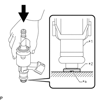
With the notch of a new No. 3 fuel injector back-up ring facing downward, install each direct fuel injector assembly to the No. 3 fuel injector back-up ring as shown in the illustration.
- NOTICE:
- ·
Make sure that the No. 3 fuel injector back-up ring is installed in the correct orientation.
·After installing the No. 3 fuel injector back-up ring, make sure there is no damage or foreign matter.
Install the nozzle holder clamp to each direct fuel injector assembly.
| *a | Protrusion |
| *b | Positioning Hole |

|
No Gap |
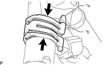
Align the protrusion of the nozzle holder clamp with the positioning hole of the fuel delivery pipe with sensor assembly LH and fuel delivery pipe RH, and insert the direct fuel injector assembly.
- NOTICE:
- ·
Make sure that there is no foreign matter or damage inside the direct fuel injector assembly installation holes (fuel delivery pipe with sensor assembly LH and fuel delivery pipe RH).
·Do not allow gasoline to get on the O-rings or inside the installation holes.
·If it is difficult to insert the direct fuel injector assembly, apply new engine oil to the chamfer of the direct fuel injector assembly installation hole of the fuel delivery pipe with sensor assembly LH and fuel delivery pipe RH. Be careful not to allow the direct fuel injector assembly to fall out of the fuel delivery pipe with sensor assembly LH or fuel delivery pipe RH.
·Do not tilt the direct fuel injector assembly when inserting it into the fuel delivery pipe with sensor assembly LH and fuel delivery pipe RH.
·Check that there is no gap between the fuel delivery pipe with sensor assembly LH, fuel delivery pipe RH and the nozzle holder clamp.
·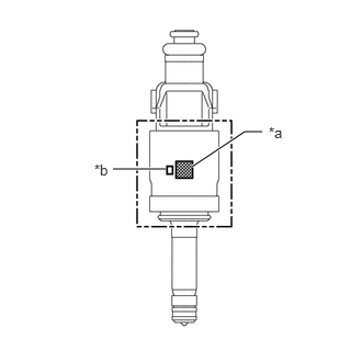 1.073,1.604 1.573,1.604 true 1.823,1.583 2.323,1.25 2.323,1.25 2.49,1.25 true 2.552,1.177 2.865,1.333 0.313,0.156 10 false *a 0.896,1.531 1.208,1.688 0.313,0.156 10 false *b
*a QR Code *b Flow Classification Number
Install 3 direct fuel injector assemblies with the same flow classification number (the number to the left of the QR code which is 6, 7 or 8) on each bank (6 fuel injector assemblies with the same flow classification number is also okay).
23814E
3.INSTALL FUEL DELIVERY PIPE RH
Connect the 3 connectors and install the No. 6 engine wire.
Apply lubricant to the direct fuel injector assembly installation holes of the cylinder head sub-assembly.
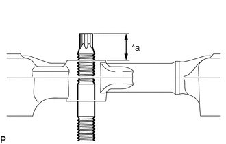
| *a | Nut can be attached |
Insert the stud bolt into the fuel delivery pipe until the screw threads protrude enough so that a nut can be attached.
- NOTICE:
- ·
If a direct fuel injector assembly is dropped or the tip of a direct fuel injector assembly is struck, replace it with a new one.
·Check that there is no foreign matter or damage on the direct fuel injector assembly installation holes of the cylinder head sub-assembly.
·When installing the fuel delivery pipe RH, push it in evenly without tilting it.
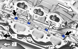
| *1 | Bolt |
| *2 | Nut |
| *a | Front |
Install the fuel delivery pipe RH by uniformly tightening the 2 bolts and 2 nuts in several passes in the order shown in the illustration.
- Torque:
- 26 N*m (265 kgf*cm, 19 ft.*lbf)
Attach the clamp to connect the No. 6 engine wire to the fuel delivery pipe RH.
Install the bolt.
- Torque:
- 10 N*m (102 kgf*cm, 7 ft.*lbf)
23860
4.INSTALL FUEL DELIVERY PIPE WITH SENSOR ASSEMBLY LH
Connect the 3 connectors and install the No. 7 engine wire.
Apply lubricant to the direct fuel injector assembly installation holes of the cylinder head LH.
Using an E8 "TORX" socket wrench, install the 2 stud bolts to the cylinder head LH.
- Torque:
- 10 N*m (102 kgf*cm, 7 ft.*lbf)
| *a | Nut can be attached |
Insert the stud bolt into the fuel delivery pipe until the screw threads protrude enough so that a nut can be attached.
- NOTICE:
- ·
If a direct fuel injector assembly is dropped or the tip of a direct fuel injector assembly is struck, replace it with a new one.
·Check that there is no foreign matter or damage on the direct fuel injector assembly installation holes of the cylinder head LH.
·When installing the fuel delivery pipe with sensor assembly LH, push it in evenly without tilting it.
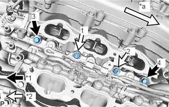
| *1 | Bolt |
| *2 | Nut |
| *a | Front |
Install the fuel delivery pipe with sensor assembly LH by uniformly tightening the 2 bolts and 2 nuts in the order shown in the illustration.
- Torque:
- 26 N*m (265 kgf*cm, 19 ft.*lbf)
Attach the clamp to connect the No. 7 engine wire to the fuel delivery pipe with sensor assembly LH.
Install the bolt.
- Torque:
- 10 N*m (102 kgf*cm, 7 ft.*lbf)
Connect the fuel pressure sensor connector.
Attach the wire harness clamp.
Connect the 2 connectors and attach the wire harness clamp.
23802B
5.INSTALL NO. 2 FUEL PIPE SUB-ASSEMBLY
Connect the No. 2 fuel pipe sub-assembly to the fuel delivery pipe with sensor assembly LH and fuel delivery pipe RH and tighten the 2 union nuts by hand.
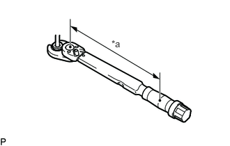
| *a | Torque Wrench Fulcrum Length |
Using a 17 mm union nut wrench, tighten the 2 union nuts of the No. 2 fuel pipe sub-assembly.
- Torque:
- Specified tightening torque : 35 N*m (357 kgf*cm, 26 ft.*lbf)
- NOTICE:
- ·
If the 2 union nuts cannot be fastened, loosen the nuts of the fuel delivery pipe with sensor assembly LH and fuel delivery pipe RH, and then fasten both union nuts.
·Do not adjust the torque in the loosening direction.
·The No. 2 fuel pipe sub-assembly can be reused 10 times.
- HINT:
- ·
Calculate the torque wrench reading when changing the fulcrum length of the torque wrench.
·When using a 17 mm union nut wrench (fulcrum length of 30 mm (1.18 in.)) + torque wrench (fulcrum length of 180 mm (7.09 in.)): 30 N*m (306 kgf*cm, 22 ft.*lbf)
·This torque value is effective when the union nut wrench is parallel to the torque wrench.
·Install the union nut wrench parallel with the torque wrench.
23100X
6.INSTALL FUEL (ENGINE ROOM SIDE) PUMP ASSEMBLY (for High Pressure)
7.CONNECT CABLE TO NEGATIVE BATTERY TERMINAL
8. INITIALIZATION AFTER RECONNECTING BATTERY TERMINAL
- HINT:
-
When disconnecting and reconnecting the battery, there is an automatic learning function that completes learning when the respective system is used.
9.INSPECT FOR FUEL LEAK