CRUISE CONTROL FRONT CAMERA SYSTEM C1A7587 Steering Vibrator System Missing Message
DESCRIPTION
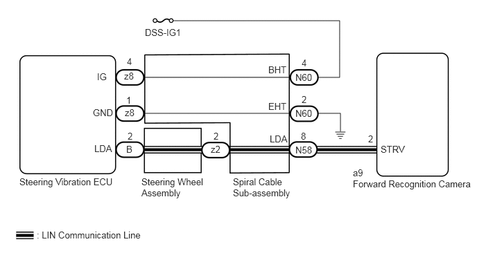
The forward recognition camera communicates with the steering vibration ECU via LIN communication.
If a communication error between the forward recognition camera and steering vibration ECU is detected, DTC C1A7587 is stored.
| DTC No. | Detection Item | DTC Detection Condition | Trouble Area |
|---|---|---|---|
| C1A7587 | Steering Vibrator System Missing Message | While the vehicle is being driven at 5 km/h (4 mph) or more and the lane control system is on, a LIN communication error is detected between the steering vibration ECU and forward recognition camera for approximately 5 minutes or more. | ·
Forward recognition camera ·
Steering vibration ECU ·
Wire harness or connector ·
Spiral cable sub-assembly |
WIRING DIAGRAM
CAUTION / NOTICE / HINT
- NOTICE:
- ·
When replacing the forward recognition camera, always replace it with a new one. If a forward recognition camera which was installed to another vehicle is used, the information stored in the forward recognition camera will not match the information from the vehicle. As a result, a DTC may be stored.
·If the forward recognition camera has been replaced with a new one, be sure to perform forward recognition camera adjustment.
- HINT:
-
Forward recognition camera adjustment can be performed by using either One Time Recognition or Sequential Recognition.
-
One Time Recognition: Click hereEngine / Hybrid System>CRUISE CONTROL>FRONT CAMERA>ADJUSTMENT (ONE TIME RECOGNITION)201902,201906,_51,_078884,_0384728,RM100000001GI2G,201906,202208,_51,_078884,_0384728,RM100000001IUI2,202208,999999,_51,_078884,_0384728,RM1000000024I1G,
-
Sequential Recognition: Click hereEngine / Hybrid System>CRUISE CONTROL>FRONT CAMERA>ADJUSTMENT (SEQUENTIAL RECOGNITION)201902,201906,_51,_078884,_0384728,RM100000001GI2H,201906,202208,_51,_078884,_0384728,RM100000001IULT,202208,999999,_51,_078884,_0384728,RM1000000024I1H,
·The vehicle is equipped with a Supplemental Restraint System (SRS) which includes components such as airbags. Before servicing (including removal or installation of parts), be sure to read the precaution for Supplemental Restraint System.
for Type B: Click hereVehicle Interior>SUPPLEMENTAL RESTRAINT SYSTEMS>AIRBAG SYSTEM (for Type B)>PRECAUTION201902,202310,_58,_079257,_0385034,RM100000001GJPR,202310,999999,_58,_079257,_0385034,RM100000002G3NC,
PROCEDURE
Inspect the spiral cable sub-assembly.
- Result:
Proceed to OK NG
OK
NG
Turn the ignition switch off.
Disconnect the N58 spiral cable sub-assembly connector.
Turn the ignition switch to ON.
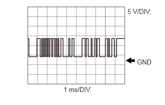
Using an oscilloscope, measure the waveform at N58 spiral cable sub-assembly connector.
- Measurement Condition:
Tester Connection Condition Tester Range N58-8 (LDA) - Body ground Ignition switch ON 5 V/DIV., 1 ms/DIV.
- NOTICE:
-
The oscilloscope waveform is for reference only and does not include noise, fluctuations, etc.
- OK:
A waveform similar to that in the illustration can be observed.
Connect the N58 spiral cable sub-assembly connector.
- Result:
Proceed to OK NG
OK
NG
Disconnect the N60 spiral cable sub-assembly connector.
Measure the voltage according to the value(s) in the table below.
- Standard Voltage:
Tester Connection Condition Specified Condition N60-4 (BHT) - Body ground Ignition switch ON 11 to 14 V
Connect the N60 spiral cable sub-assembly connector.
- Result:
Proceed to OK NG
OK
NG
Turn the ignition switch off.
Disconnect the N60 spiral cable sub-assembly connector.
Measure the resistance according to the value(s) in the table below.
- Standard Resistance:
Tester Connection Condition Specified Condition N60-2 (EHT) - Body ground Always Below 1 Ω
Connect the N60 spiral cable sub-assembly connector.
- Result:
Proceed to OK NG
OK
NG
Turn the ignition switch off.
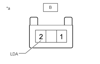
| *a | Front view of wire harness connector
(to Steering Vibration ECU) |
Disconnect the z2 spiral cable sub-assembly connector.
Disconnect the B steering vibration ECU connector.
Measure the resistance according to the value(s) in the table below.
- Standard Resistance:
Tester Connection Condition Specified Condition z2-2 (LDA) - B-2 (LDA) Always Below 1 Ω z2-2 (LDA) or B-2 (LDA) - Body ground Ignition switch off 10 kΩ or higher
Connect the B steering vibration ECU connector.
Connect the z2 spiral cable sub-assembly connector.
- Result:
Proceed to OK NG
OK
NG
Turn the ignition switch off.
Disconnect the a9 forward recognition camera connector.
Disconnect the N58 spiral cable sub-assembly connector.
Measure the resistance according to the value(s) in the table below.
- Standard Resistance:
Tester Connection Condition Specified Condition N58-8 (LDA) - a9-2 (STRV) Always Below 1 Ω N58-8 (LDA) or a9-2 (STRV) - Body ground Ignition switch off 10 kΩ or higher
Connect the N58 spiral cable sub-assembly connector.
Connect the a9 forward recognition camera connector.
- Result:
Proceed to OK NG
OK
NG