SUPPLEMENTAL RESTRAINT SYSTEMS SPIRAL CABLE INSPECTION
PROCEDURE

 1.INSPECT SPIRAL CABLE SUB-ASSEMBLY (for Dual Type)
- NOTICE:
- ·
Do not remove the steering sensor from the spiral cable sub-assembly when inspecting the spiral cable sub-assembly.
- ·
Remove the steering sensor from the spiral cable sub-assembly only when replacing the spiral cable sub-assembly.
Visually check the spiral cable sub-assembly for defects.
The defects are as follows:
Scratches
Small cracks
Dents
Chips
Cracks or other damage to the connector
- OK:
No defects are found.
If any defects are found, replace the spiral cable sub-assembly with a new one.
Check the spiral cable sub-assembly.
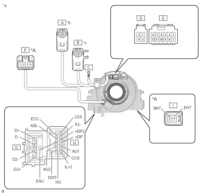
| *A | w/ Steering Vibration | - | - |
| *a | Component without harness connected
(Spiral Cable Sub-assembly) |
*b | Color: Light Green |
| *c | Color: Black | - | - |

|
Interlock | - | - |
- NOTICE:
- ·
When rotating the spiral cable sub-assembly, make sure to push on the interlock shown in the illustration to release the interlock mechanism.
·As the spiral cable sub-assembly may break, do not rotate the spiral cable sub-assembly more than the specified amount.
Set the spiral cable sub-assembly to the center position.
Measure the resistance between each terminal of the spiral cable sub-assembly according to the value(s) in the table below.
After setting the spiral cable sub-assembly to the center position, rotate the spiral cable sub-assembly 2.5 times clockwise, and measure the resistance according to the value(s) in the table below. Then rotate the spiral cable sub-assembly 5 times counterclockwise, and measure the resistance according to the value(s) in the table below.
After setting the spiral cable sub-assembly to the center position, rotate the spiral cable sub-assembly 2.5 times clockwise. Then while rotating the spiral cable sub-assembly 5 times counterclockwise, measure the resistance according to the value(s) in the table below.
Inspect the SRS airbag circuit.
- Standard Resistance:
Tester Connection Condition Specified Condition If the result is not as specified, replace the spiral cable sub-assembly.
G-1 (D+) - A-2 Always Below 1.3 Ω G-2 (D-) - A-1 Always Below 1.3 Ω G-3 (D2-) - B-1 Always Below 1.3 Ω G-4 (D2+) - B-2 Always Below 1.3 Ω
Inspect the horn circuit.
- Standard Resistance:
Tester Connection Condition Specified Condition If the result is not as specified, replace the spiral cable sub-assembly.
H-7 (HO) - C Always 3 Ω or less
Inspect the steering pad switch circuit.
- Standard Resistance:
Tester Connection Condition Specified Condition If the result is not as specified, replace the spiral cable sub-assembly.
H-4 (EAU) - E-10 Always 3 Ω or less H-5 (AU2) - E-9 Always 3 Ω or less H-9 (ILL-) - E-6 Always 3 Ω or less H-10 (+DP2) - E-5 Always 3 Ω or less H-11 (+DP) - E-4 Always 3 Ω or less H-12 (AU1) - E-3 Always 3 Ω or less H-14 (IL+2) - E-1 Always 3 Ω or less
Inspect the cruise control circuit.
- Standard Resistance:
Tester Connection Condition Specified Condition If the result is not as specified, replace the spiral cable sub-assembly.
H-2 (ECC) - E-12 Always 3 Ω or less H-3 (ASL) - E-11 Always 3 Ω or less H-6 (DIST) - E-8 Always 3 Ω or less H-13 (CCS) - E-2 Always 3 Ω or less
Inspect the steering vibration circuit.
- Standard Resistance:
Tester Connection Condition Specified Condition If the result is not as specified, replace the spiral cable sub-assembly.
H-8 (LDA) - D-2 Always Below 0.08 Ω I-2 (EHT) - F-1 Always Below 0.08 Ω I-4 (BHT) - F-4 Always Below 0.08 Ω
2.INSPECT SPIRAL CABLE SUB-ASSEMBLY (for Single Type)
- NOTICE:
- ·
Do not remove the steering sensor from the spiral cable sub-assembly when inspecting the spiral cable sub-assembly.
- ·
Remove the steering sensor from the spiral cable sub-assembly only when replacing the spiral cable sub-assembly.
Visually check the spiral cable sub-assembly for defects.
The defects are as follows:
Scratches
Small cracks
Dents
Chips
Cracks or other damage to the connector
- OK:
No defects are found.
If any defects are found, replace the spiral cable sub-assembly with a new one.
Check the spiral cable sub-assembly.

| *A | w/ Steering Vibration | - | - |
| *a | Component without harness connected
(Spiral Cable Sub-assembly) |
- | - |
|
|
Interlock | - | - |
- NOTICE:
- ·
When rotating the spiral cable sub-assembly, make sure to push on the interlock shown in the illustration to release the interlock mechanism.
·As the spiral cable sub-assembly may break, do not rotate the spiral cable sub-assembly more than the specified amount.
Set the spiral cable sub-assembly to the center position.
Measure the resistance between each terminal of the spiral cable sub-assembly according to the value(s) in the table below.
After setting the spiral cable sub-assembly to the center position, rotate the spiral cable sub-assembly 2.5 times clockwise, and measure the resistance according to the value(s) in the table below. Then rotate the spiral cable sub-assembly 5 times counterclockwise, and measure the resistance according to the value(s) in the table below.
After setting the spiral cable sub-assembly to the center position, rotate the spiral cable sub-assembly 2.5 times clockwise. Then while rotating the spiral cable sub-assembly 5 times counterclockwise, measure the resistance according to the value(s) in the table below.
Inspect the SRS airbag circuit.
- Standard Resistance:
Tester Connection Condition Specified Condition If the result is not as specified, replace the spiral cable sub-assembly.
F-1 (D+) - A-2 Always Below 1.3 Ω F-2 (D-) - A-1 Always Below 1.3 Ω
Inspect the horn circuit.
- Standard Resistance:
Tester Connection Condition Specified Condition If the result is not as specified, replace the spiral cable sub-assembly.
G-7 (HO) - B Always 3 Ω or less
Inspect the steering pad switch circuit.
- Standard Resistance:
Tester Connection Condition Specified Condition If the result is not as specified, replace the spiral cable sub-assembly.
G-4 (EAU) - D-10 Always 3 Ω or less G-5 (AU2) - D-9 Always 3 Ω or less G-9 (ILL-) - D-6 Always 3 Ω or less G-10 (+DP2) - D-5 Always 3 Ω or less G-11 (+DP) - D-4 Always 3 Ω or less G-12 (AU1) - D-3 Always 3 Ω or less G-14 (IL+2) - D-1 Always 3 Ω or less
Inspect the cruise control circuit.
- Standard Resistance:
Tester Connection Condition Specified Condition If the result is not as specified, replace the spiral cable sub-assembly.
G-2 (ECC) - D-12 Always 3 Ω or less G-3 (ASL) - D-11 Always 3 Ω or less G-6 (DIST) - D-8 Always 3 Ω or less G-13 (CCS) - D-2 Always 3 Ω or less
Inspect the steering vibration circuit.
- Standard Resistance:
Tester Connection Condition Specified Condition If the result is not as specified, replace the spiral cable sub-assembly.
G-8 (LDA) - H-2 Always Below 0.08 Ω H-2 (EHT) - E-1 Always Below 0.08 Ω H-4 (BHT) - E-4 Always Below 0.08 Ω