STEERING COLUMN STEERING WHEEL REMOVAL
CAUTION / NOTICE / HINT
The necessary procedures (adjustment, calibration, initialization, or registration) that must be performed after parts are removed, installed, or replaced during steering wheel assembly removal/installation are shown below.
| Replaced Part or Performed Procedure | Necessary Procedure | Effect/Inoperative Function when Necessary Procedure not Performed | Link |
|---|---|---|---|
| Battery terminal is disconnected/reconnected | Memorize steering angle neutral point | Parking assist monitor system | ( 201902,999999,_56,_079315,_0385736,RM100000001GNRA,) 201902,999999,_56,_079315,_0385736,RM100000001GNRA,)
|
| Panoramic view monitor system | (201906,999999,_56,_079315,_0396274,RM100000001IGR3,)
|
- HINT:
- ·
When the cable is disconnected / reconnected to the battery terminal, systems temporarily stop operating. However, each system has a function that completes learning the first time the system is used.
-Learning completes when vehicle is driven
Effect/Inoperative when not Performed Necessary Procedures Link Stop and start system Drive the vehicle until stop and start control is permitted (approximately 5 to 60 minutes). ( 201902,999999,_51,_078825,_0382334,RM100000001GBQ1,)
Lane control system Drive the vehicle straight ahead at 15 km/h (10 mph) or more for 1 second or more. ( 201902,999999,_58,_078886,_0382740,RM100000001G6XB,)
Pre-collision system
-Learning completes when vehicle is operated normally
Effect/Inoperative when not Performed Necessary Procedures Link Power slide door system Fully close the slide door by hand.
- HINT:
-
Initialization is not necessary if the above procedures are performed while the slide door is closed.
( 201902,999999,_59,_078503,_0381017,RM100000001FWXM,)
Air conditioning system After the ignition switch is turned to ON, the servo motor standard position is recognized. -
·Use the same procedure for RHD and LHD vehicles.
·The procedure listed below is for LHD vehicles.
PROCEDURE

 1. PRECAUTION
- CAUTION:
-
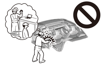
-
Be sure to read precaution thoroughly before servicing.
- ··
- NOTICE:
-
After turning the ignition switch off, waiting time may be required before disconnecting the cable from the negative (-) battery terminal.
2.PLACE FRONT WHEELS FACING STRAIGHT AHEAD
3.DISCONNECT CABLE FROM NEGATIVE BATTERY TERMINAL
- CAUTION:
- ·
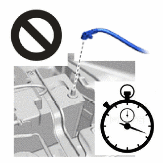
Wait at least 90 seconds after disconnecting the cable from the negative (-) battery terminal to disable the SRS system.
·If the airbag deploys for any reason, it may cause a serious accident.
45130
4.REMOVE HORN BUTTON ASSEMBLY
84250A
5.REMOVE STEERING PAD SWITCH ASSEMBLY (w/ Steering Pad Switch)
45116
6.REMOVE NO. 1 STEERING WHEEL ORNAMENT (w/o Steering Pad Switch)
- HINT:
-
Use the same procedure described for the steering pad switch assembly.
45100
7.REMOVE STEERING WHEEL ASSEMBLY
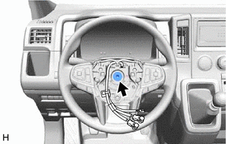
Remove the steering wheel set bolt.
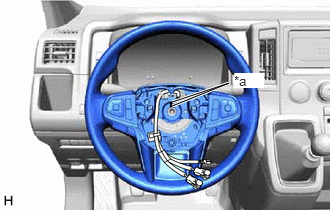
| *a | Matchmark |
Put matchmarks on the steering wheel and steering main shaft.
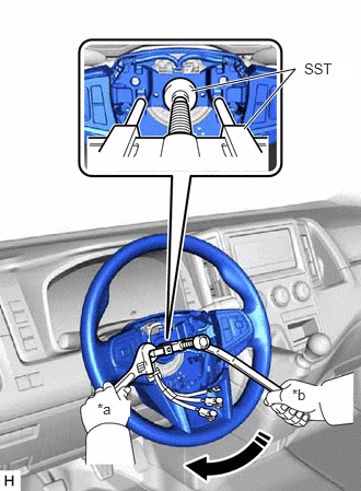
| *a | Hold |
| *b | Turn |
Using SST, remove the steering wheel assembly.
- SST
- 09950-50013 (09951-05010, 09952-05010, 09953-05020, 09954-05031, 09957-04010)
09950-60011 (09951-00330)
- NOTICE:
-
Apply a small amount of grease to the threads and tip of SST (09953-05020) before use.
45184
8.REMOVE LOWER STEERING WHEEL BOSS COVER
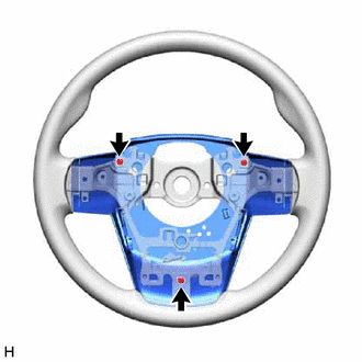
Remove the 3 screws.
Remove the lower steering wheel boss cover from the steering wheel assembly.
864A2
9.REMOVE STEERING VIBRATION ECU (w/ Lane Departure Alert System)