RM35X0E _51 Engine / Hybrid System _078884 CRUISE CONTROL _0382737 SPEED LIMITER SYSTEM J

CRUISE CONTROL  SPEED LIMITER SYSTEM  Speed Limiter System does not Operate  


DESCRIPTION

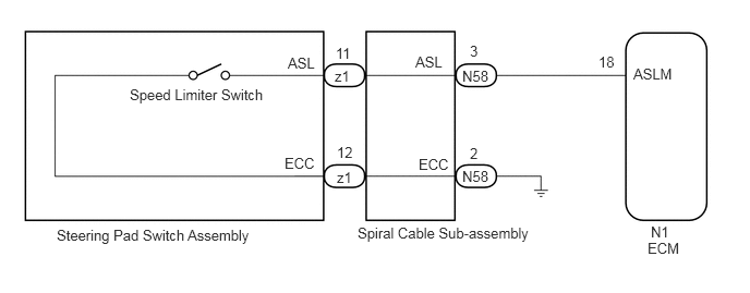
When the speed limiter is turned on using the speed limiter switch, the ECM illuminates the speed limiter indicator and activates the speed limiter system. Each function of the speed limiter system can be activated by operating the steering switch. When the cruise control system is operating, the speed limiter system will not operate.

WIRING DIAGRAM
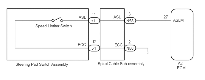
for 1GD-FTV:
C414307E02
1.24,0.823 2.708,1.052 1.469,0.229 10 false Speed Limiter Switch 3.198,0.646 3.51,0.844 0.313,0.198 10 false z1 3.208,0.427 3.521,0.625 0.313,0.198 10 false 11 3.219,1.615 3.531,1.813 0.313,0.198 10 false z1 3.219,1.375 3.531,1.573 0.313,0.198 10 false 12 0.542,2.167 2.615,2.552 2.073,0.385 10 false Steering Pad Switch Assembly 3.969,0.51 4.344,0.708 0.375,0.198 10 false ASL 4,1.49 4.375,1.688 0.375,0.198 10 false ECC 4.417,0.646 4.792,0.844 0.375,0.198 10 false N58 4.417,1.604 4.792,1.802 0.375,0.198 10 false N58 4.49,0.406 4.802,0.604 0.313,0.198 10 false 3 4.49,1.385 4.802,1.583 0.313,0.198 10 false 2 5.719,0.51 5.969,0.719 0.25,0.208 10 false 27 6.052,0.625 6.531,0.813 0.479,0.188 10 false ASLM 6.188,2.292 6.667,2.49 0.479,0.198 10 false ECM 6.219,2.135 6.698,2.333 0.479,0.198 10 false A2 3.417,2.146 5.167,2.406 1.75,0.26 10 false Spiral Cable Sub-assembly 2.75,0.521 3.125,0.719 0.375,0.198 10 false ASL 2.719,1.479 3.094,1.677 0.375,0.198 10 false ECC

for 7GR-FKS:
C414307E03
1.24,0.823 2.708,1.052 1.469,0.229 10 false Speed Limiter Switch 3.198,0.646 3.51,0.844 0.313,0.198 10 false z1 3.208,0.427 3.521,0.625 0.313,0.198 10 false 11 3.219,1.615 3.531,1.813 0.313,0.198 10 false z1 3.219,1.375 3.531,1.573 0.313,0.198 10 false 12 0.542,2.167 2.615,2.552 2.073,0.385 10 false Steering Pad Switch Assembly 3.969,0.51 4.344,0.708 0.375,0.198 10 false ASL 4,1.49 4.375,1.688 0.375,0.198 10 false ECC 4.417,0.646 4.792,0.844 0.375,0.198 10 false N58 4.417,1.604 4.792,1.802 0.375,0.198 10 false N58 4.49,0.406 4.802,0.604 0.313,0.198 10 false 3 4.49,1.385 4.802,1.583 0.313,0.198 10 false 2 5.719,0.51 5.969,0.719 0.25,0.208 10 false 18 6.052,0.625 6.531,0.813 0.479,0.188 10 false ASLM 6.188,2.292 6.667,2.49 0.479,0.198 10 false ECM 6.219,2.135 6.698,2.333 0.479,0.198 10 false N1 3.417,2.146 5.167,2.406 1.75,0.26 10 false Spiral Cable Sub-assembly 2.75,0.521 3.125,0.719 0.375,0.198 10 false ASL 2.719,1.479 3.094,1.677 0.375,0.198 10 false ECC

PROCEDURE

1.CHECK CRUISE CONTROL SYSTEM
a.

Turn the ignition switch to ON.


b.

Turn the cruise control on using the cruise control main switch.


c.

Check the operation of each function by operating the cruise control main switch.

Click hereEngine / Hybrid System>CRUISE CONTROL>CRUISE CONTROL SYSTEM>ROAD TEST

OK:

Each function of the cruise control system operates normally.


Result:
Proceed to
OK
NG


OK

2.READ VALUE USING GTS (ASL SW)

NG

2.READ VALUE USING GTS (ASL SW)
a.

Connect the GTS to the DLC3.


b.

Turn the ignition switch to ON.


c.

Turn the GTS on.


d.

Enter the following menus: Powertrain / Engine / Data List / ASL SW.


e.

According to the display on the GTS, read the Data List.

Powertrain > Engine > Data List
Tester Display Measurement Item Range Normal Condition Diagnostic Note
ASL SW Speed limiter switch signal ON or OFF OFF: Speed limiter switch off
ON: Speed limiter switch on
-
Powertrain > Engine > Data List
Tester Display
ASL SW
50003 372 380
OK:

The Data List item ASL SW changes according to the operation of the switch.


Result:
Proceed to
OK
NG


OK

NG

3.CHECK HARNESS AND CONNECTOR (SPIRAL CABLE SUB-ASSEMBLY - ECM)
a.

for 7GR-FKS:

i.

Disconnect the N1 ECM connector.


ii.

Disconnect the N58 spiral cable sub-assembly connector.


iii.

Measure the resistance according to the value(s) in the table below.

Standard Resistance:
Tester Connection Condition Specified Condition
N1-18 (ASLM) - N58-3 (ASL) Always Below 1 Ω
N1-18 (ASLM) or N58-3 (ASL) - Body ground Always 10 kΩ or higher
N58-2 (ECC) - Body ground Always Below 1 Ω


b.

for 1GD-FTV:

i.

Disconnect the A2 ECM connector.


ii.

Disconnect the N58 spiral cable sub-assembly connector.


iii.

Measure the resistance according to the value(s) in the table below.

Standard Resistance:
Tester Connection Condition Specified Condition
A2-27 (ASLM) - N58-3 (ASL) Always Below 1 Ω
A2-27 (ASLM) or N58-3 (ASL) - Body ground Always 10 kΩ or higher
N58-2 (ECC) - Body ground Always Below 1 Ω


Result:
Proceed to
OK
NG


OK

4.INSPECT SPIRAL CABLE SUB-ASSEMBLY

NG

REPAIR OR REPLACE HARNESS OR CONNECTOR