BRAKE CONTROL / DYNAMIC CONTROL SYSTEMS ELECTRONICALLY CONTROLLED BRAKE SYSTEM(for HEV Model) C05621C Brake Pedal Position Sensor Supply Voltage Circuit Voltage Out of Range C139200 Zero Point Calibration of Stroke Sensor P057A11 Brake Pedal Position Sensor "A" Circuit Short to Ground P057A15 Brake Pedal Position Sensor "A" Circuit Short to Battery or Open P057A28 Brake Pedal Position Sensor "A" Signal Bias Level Out of Range / Zero Adjustment Failure P057A64 Brake Pedal Position Sensor "A" Signal Plausibility Failure P05DB11 Brake Pedal Position Sensor "B" Circuit Short to Ground P05DB15 Brake Pedal Position Sensor "B" Circuit Short to Battery or Open P05DB28 Brake Pedal Position Sensor "B" Signal Bias Level Out of Range / Zero Adjustment Failure P05DB64 Brake Pedal Position Sensor "B" Signal Plausibility Failure P05E064 Brake Pedal Position Sensor "A"/"B" Signal Plausibility Failure P157A62 Brake Pedal Position Sensor "A" / "B" Brake Master Cylinder Pressure Sensor Multiple Sensor Signal Compare Failure
DESCRIPTION
The brake pedal stroke sensor assembly sends the brake pedal stroke distance to the skid control ECU inside the brake actuator assembly.
| DTC No. | Detection Item | DTC Detection Condition | Trouble Area | MIL | DTC Output from | Note |
|---|---|---|---|---|---|---|
| C05621C | Brake Pedal Position Sensor Supply Voltage Circuit Voltage Out of Range | Brake pedal stroke sensor assembly power source malfunction detected. | ·
Brake pedal stroke sensor assembly ·
Skid control ECU (brake actuator assembly) |
Does not come on | Brake/EPB | Output ECU: Skid control ECU (brake actuator assembly) |
| C139200 | Zero Point Calibration of Stroke Sensor | While the brake pedal is not being depressed, brake pedal stroke sensor assembly zero point not calibrated signal is received. (A correct brake pedal stroke sensor assembly zero point learning value is not present). | ·
Brake pedal stroke sensor assembly ·
Skid control ECU (brake actuator assembly) |
Does not come on | Brake/EPB | Output ECU: Skid control ECU (brake actuator assembly) |
| P057A11 | Brake Pedal Position Sensor "A" Circuit Short to Ground | Open or short detected due to abnormality in brake pedal stroke sensor assembly output circuit 1. | ·
Brake pedal stroke sensor assembly ·
Skid control ECU (brake actuator assembly) |
Does not come on | Brake/EPB | Output ECU: Skid control ECU (brake actuator assembly) |
| P057A15 | Brake Pedal Position Sensor "A" Circuit Short to Battery or Open | Open or short detected due to abnormality in brake pedal stroke sensor assembly output circuit 1. | ·
Brake pedal stroke sensor assembly ·
Skid control ECU (brake actuator assembly) |
Does not come on | Brake/EPB | Output ECU: Skid control ECU (brake actuator assembly) |
| P057A28 | Brake Pedal Position Sensor "A" Signal Bias Level Out of Range / Zero Adjustment Failure | Difference in change amount of brake pedal stroke sensor assembly output voltage 1 (SKS1) is abnormally large for 0.1 seconds or more. (SKS1 output comparison invalid). | ·
Brake pedal stroke sensor assembly ·
Skid control ECU (brake actuator assembly) |
Does not come on | Brake/EPB | Output ECU: Skid control ECU (brake actuator assembly) |
| P057A64 | Brake Pedal Position Sensor "A" Signal Plausibility Failure | Difference in change amount of brake pedal stroke sensor assembly output voltage 1 (SKS1) is abnormally large for 0.2 seconds or more. (SKS1 output comparison invalid). | ·
Brake pedal stroke sensor assembly ·
Skid control ECU (brake actuator assembly) |
Does not come on | Brake/EPB | Output ECU: Skid control ECU (brake actuator assembly) |
| P05DB11 | Brake Pedal Position Sensor "B" Circuit Short to Ground | Open or short detected due to abnormality in brake pedal stroke sensor assembly output circuit 2. | ·
Brake pedal stroke sensor assembly ·
Skid control ECU (brake actuator assembly) |
Does not come on | Brake/EPB | Output ECU: Skid control ECU (brake actuator assembly) |
| P05DB15 | Brake Pedal Position Sensor "B" Circuit Short to Battery or Open | Open or short detected due to abnormality in brake pedal stroke sensor assembly output circuit 2. | ·
Brake pedal stroke sensor assembly ·
Skid control ECU (brake actuator assembly) |
Does not come on | Brake/EPB | Output ECU: Skid control ECU (brake actuator assembly) |
| P05DB28 | Brake Pedal Position Sensor "B" Signal Bias Level Out of Range / Zero Adjustment Failure | Difference in change amount of brake pedal stroke sensor assembly output voltage 2 (SKS2) is abnormally large for 0.1 seconds or more. (SKS2 output comparison invalid). | ·
Brake pedal stroke sensor assembly ·
Skid control ECU (brake actuator assembly) |
Does not come on | Brake/EPB | Output ECU: Skid control ECU (brake actuator assembly) |
| P05DB64 | Brake Pedal Position Sensor "B" Signal Plausibility Failure | Difference in change amount of brake pedal stroke sensor assembly output voltage 2 (SKS2) is abnormally large for 0.2 seconds or more. (SKS2 output comparison invalid). | ·
Brake pedal stroke sensor assembly ·
Skid control ECU (brake actuator assembly) |
Does not come on | Brake/EPB | Output ECU: Skid control ECU (brake actuator assembly) |
| P05E064 | Brake Pedal Position Sensor "A"/"B" Signal Plausibility Failure | Difference between change amounts of brake pedal stroke sensor assembly output voltage 1 (SKS1) and brake pedal stroke sensor assembly output voltage 2 (SKS2) is abnormally large for 0.2 seconds or more. (SKS1 and SKS2 output comparison invalid). | ·
Brake pedal stroke sensor assembly ·
Skid control ECU (brake actuator assembly) |
Does not come on | Brake/EPB | Output ECU: Skid control ECU (brake actuator assembly) |
| P157A62 | Brake Pedal Position Sensor "A" / "B" Brake Master Cylinder Pressure Sensor Multiple Sensor Signal Compare Failure | While driving at a vehicle speed of 3 km/h or more, the master cylinder pressure sensor value is too high relative to the brake pedal stroke sensor assembly value for 0.2 seconds or more. | ·
Brake pedal stroke sensor assembly ·
Skid control ECU (brake actuator assembly) |
Does not come on | Brake/EPB | Output ECU: Skid control ECU (brake actuator assembly) |
WIRING DIAGRAM
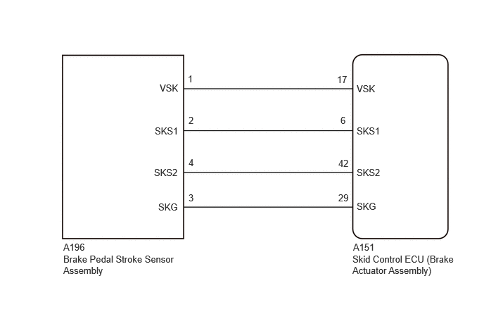
PROCEDURE
Check that the brake pedal and the brake pedal stroke sensor assembly are properly installed and that the pedal can be depressed normally.
Check and adjust the brake pedal height.
Adjust the brake pedal stroke sensor assembly.
- Result:
Proceed to NEXT
NEXT
Read the DTCs using the GTS.
- Chassis > Brake/EPB > Trouble Codes
- 50001 435
- Result:
Result Proceed to C05621C, C139200, P057A11, P057A15, P057A28, P057A64, P05DB11, P05DB15, P05DB28, P05DB64, P05E064 or P157A62 is output A Only C139200 is output B None of the above conditions are met C
A
B
C
Turn the ignition switch off.
Make sure that there is no looseness at the locking part and the connecting part of the connectors.
- OK:
The connector is securely connected.
Disconnect the A151 skid control ECU (Brake Actuator Assembly) connector.
Disconnect the A196 brake pedal stroke sensor assembly connector.
Check both the connector case and the terminals for deformation and corrosion.
- OK:
No deformation or corrosion.
Measure the resistance according to the value(s) in the table below.
- Standard Resistance:
Tester Connection Condition Specified Condition A151-17 (VSK) - A196-1 (VSK) Always Below 1 Ω A151-17 (VSK) or A196-1 (VSK) - Body ground Always 10 kΩ or higher A151-6 (SKS1) - A196-2 (SKS1) Always Below 1 Ω A151-6 (SKS1) or A196-2 (SKS1) - Body ground Always 10 kΩ or higher A151-42 (SKS2) - A196-4 (SKS2) Always Below 1 Ω A151-42 (SKS2) or A196-4 (SKS2) - Body ground Always 10 kΩ or higher A151-29 (SKG) - A196-3 (SKG) Always Below 1 Ω A151-29 (SKG) or A196-3 (SKG) - Body ground Always 10 kΩ or higher
- Result:
Proceed to OK NG
OK
NG
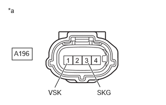
| *a | Front view of wire harness connector
(to Brake Pedal Stroke Sensor Assembly) |
Make sure that there is no looseness at the locking part and the connecting part of the connectors.
- OK:
The connector is securely connected.
Disconnect the A196 brake pedal stroke sensor assembly connector.
Check both the connector case and the terminals for deformation and corrosion.
- OK:
No deformation or corrosion.
Turn the ignition switch to ON.
Measure the voltage according to the value(s) in the table below.
- Standard Voltage:
Tester Connection Condition Specified Condition A196-1 (VSK) - A196-3 (SKG) Ignition switch ON 4.84 to 5.16 V
- Result:
Proceed to OK NG
OK
NG
Using the GTS, clear the brake pedal stroke sensor assembly zero point.
- Chassis > Brake/EPB > Utility
-
Tester Display Reset Memory - 50005 435 4560
- Result:
Proceed to NEXT
NEXT
Using the GTS, perform the brake pedal stroke sensor assembly zero point calibration.
- Chassis > Brake/EPB > Utility
-
Tester Display Calibration - 50005 435 4554
- Result:
Proceed to NEXT
NEXT
Clear the DTCs.
- Chassis > Brake/EPB > Clear DTCs
- 50002 435
Turn the ignition switch off.
- Result:
Proceed to NEXT
NEXT
Based on the Freeze Frame Data and interview with the customer, attempt to reproduce the conditions when the malfunction occurred.
Check if the same DTC is output.
- Chassis > Brake/EPB > Trouble Codes
- 50001 435
- Result:
Result Proceed to C139200 is output A DTCs are not output B None of the above conditions are met C
A
B
C
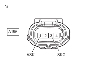
| *a | Front view of wire harness connector
(to Brake Pedal Stroke Sensor Assembly) |
Turn the ignition switch off.
Make sure that there is no looseness at the locking part and the connecting part of the connectors.
- OK:
The connector is securely connected.
Reconnect the A196 brake pedal stroke sensor assembly connector.
Check both the connector case and the terminals for deformation and corrosion.
- OK:
No deformation or corrosion.
Turn the ignition switch to ON.
Measure the voltage according to the value(s) in the table below.
- Standard Voltage:
Tester Connection Condition Specified Condition A196-1 (VSK) - A196-3 (SKG) Ignition switch ON 4.84 to 5.16 V
- Result:
Proceed to OK NG
OK
NG