PARK ASSIST / MONITORING PANORAMIC VIEW MONITOR SYSTEM(Production Date from 2023/04) Image from Camera for Panoramic View Monitor is Abnormal
DESCRIPTION
The display signal from each television camera is transmitted to the radio and display receiver assembly via the parking assist ECU.
WIRING DIAGRAM
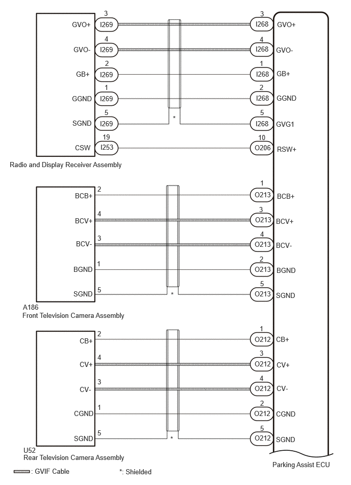
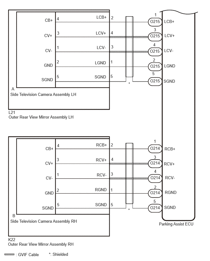
CAUTION / NOTICE / HINT
- NOTICE:
-
Depending on the parts that are replaced or operations that are performed during vehicle inspection or maintenance, calibration of other systems as well as the panoramic view monitor system may be needed.
- HINT:
- Images may be unclear even in normal conditions if:·
Electrical devices are used in the cabin (noise may occur in the image).
·The camera lens is frosted over (the image immediately after turning the ignition switch to ON may be blurred or darker than normal).
·The camera lens is dirty with snow, mud, etc.
·A strong beam of light, such as a sunbeam or headlight, hits the camera.
·It is too dark around the camera (at night, etc.).
·The ambient temperature around the camera is either too high or too low.
·The vehicle is tilted at a steep angle.
·The television camera assembly lens is scratched.
·The television camera assembly lens has drops of water on it or the humidity is high.
·When the camera is used under fluorescent lights, sodium lights, or mercury lights, etc., the lights and the illuminated area may appear to flicker.
PROCEDURE
Check if the same malfunction occurs when the panoramic view monitor screen is displayed.
- Result:
Result Proceed to Rear view screen is not displayed. A Front view screen is not displayed. B Side monitor screen (LH side) is not displayed. C Side monitor screen (RH side) is not displayed. D Panoramic view monitor screen is not displayed. E Multiple camera images are not displayed or are distorted. F
A
B
C
D
E
F
Disconnect the O212 parking assist ECU connector.
Disconnect the U52 rear television camera assembly connector.
Measure the resistance according to the value(s) in the table below.
- Standard Resistance:
Tester Connection Condition Specified Condition O212-1 (CB+) - U52-2 (CB+) Always Below 1 Ω O212-3 (CV+) - U52-4 (CV+) Always Below 1 Ω O212-4 (CV-) - U52-3 (CV-) Always Below 1 Ω O212-2 (CGND) - U52-1 (CGND) Always Below 1 Ω O212-5 (SGND) - U52-5 (SGND) Always Below 1 Ω O212-1 (CB+) or U52-2 (CB+) - Body ground Always 10 kΩ or higher O212-3 (CV+) or U52-4 (CV+) - Body ground Always 10 kΩ or higher O212-4 (CV-) or U52-3 (CV-) - Body ground Always 10 kΩ or higher O212-2 (CGND) or U52-1 (CGND) - Body ground Always 10 kΩ or higher O212-5 (SGND) - U52-5 (SGND) - Body ground Always 10 kΩ or higher
- Result:
Proceed to OK NG
OK
NG
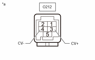
| *a | Component without harness connected
(Parking Assist ECU) |
Disconnect the O212 parking assist ECU connector.
Measure the resistance according to the value(s) in the table below.
- Standard Resistance:
Tester Connection Condition Specified Condition O212-3 (CV+) - Body ground Always 10 kΩ or higher O212-4 (CV-) - Body ground Always 10 kΩ or higher
- Result:
Proceed to OK NG
OK
NG
Disconnect the U52 rear television camera assembly connector.
Measure the resistance according to the value(s) in the table below.
- Standard Resistance:
Tester Connection Condition Specified Condition U52-1 (CGND) - Body ground Always Below 1 Ω
Measure the voltage according to the value(s) in the table below.
- Standard Voltage:
Tester Connection Switch Condition Specified Condition U52-2 (CB+) - U52-1 (CGND) Ignition switch ON 7.5 to 8.5 V
- Result:
Proceed to OK NG
OK
NG
Disconnect the O213 parking assist ECU connector.
Disconnect the A186 front television camera assembly connector.
Measure the resistance according to the value(s) in the table below.
- Standard Resistance:
Tester Connection Condition Specified Condition O213-1 (BCB+) - A186-2 (BCB+) Always Below 1 Ω O213-3 (BCV+) - A186-4 (BCV+) Always Below 1 Ω O213-4 (BCV-) - A186-3 (BCV-) Always Below 1 Ω O213-2 (BGND) - A186-1 (BGND) Always Below 1 Ω O213-5 (SGND) - A186-5 (SGND) Always Below 1 Ω O213-1 (BCB+) or A186-2 (BCB+) - Body ground Always 10 kΩ or higher O213-3 (BCV+) or A186-4 (BCV+) - Body ground Always 10 kΩ or higher O213-4 (BCV-) or A186-3 (BCV-) - Body ground Always 10 kΩ or higher O213-2 (BGND) or A186-1 (BGND) - Body ground Always 10 kΩ or higher O213-5 (SGND) or A186-5 (SGND) - Body ground Always 10 kΩ or higher
- Result:
Proceed to OK NG
OK
NG
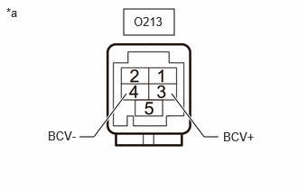
| *a | Component without harness connected
(Parking Assist ECU) |
Disconnect the O213 parking assist ECU connector.
Measure the resistance according to the value(s) in the table below.
- Standard Resistance:
Tester Connection Condition Specified Condition O213-3 (BCV+) - Body ground Always 10 kΩ or higher O213-4 (BCV-) - Body ground Always 10 kΩ or higher
- Result:
Proceed to OK NG
OK
NG
Disconnect the A186 front television camera assembly connector.
Measure the resistance according to the value(s) in the table below.
- Standard Resistance:
Tester Connection Condition Specified Condition A186-1 (BGND) - Body ground Always Below 1 Ω
Measure the voltage according to the value(s) in the table below.
- Standard Voltage:
Tester Connection Switch Condition Specified Condition A186-2 (BCB+) - A186-1 (BGND) Ignition switch ON 7.5 to 8.5 V
- Result:
Proceed to OK NG
OK
NG
Disconnect the O215 parking assist ECU connector.
Disconnect the L21 outer rear view mirror assembly LH connector.
Measure the resistance according to the value(s) in the table below.
- Standard Resistance:
Tester Connection Condition Specified Condition O215-1 (LCB+) - L21-2 (LCB+) Always Below 1 Ω O215-3 (LCV+) - L21-4 (LCV+) Always Below 1 Ω O215-4 (LCV-) - L21-3 (LCV-) Always Below 1 Ω O215-2 (LGND) - L21-1 (LGND) Always Below 1 Ω O215-5 (SGND) - L21-5 (SGND) Always Below 1 Ω O215-1 (LCB+) or L21-2 (LCB+) - Body ground Always 10 kΩ or higher O215-3 (LCV+) or L21-4 (LCV+) - Body ground Always 10 kΩ or higher O215-4 (LCV-) or L21-3 (LCV-) - Body ground Always 10 kΩ or higher O215-2 (LGND) or L21-1 (LGND) - Body ground Always 10 kΩ or higher O215-5 (SGND) or L21-5 (SGND) - Body ground Always 10 kΩ or higher
- Result:
Proceed to OK NG
OK
NG
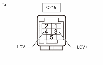
| *a | Component without harness connected
(Parking Assist ECU) |
Disconnect the O215 parking assist ECU connector.
Measure the resistance according to the value(s) in the table below.
- Standard Resistance:
Tester Connection Condition Specified Condition O215-3 (LCV+) - Body ground Always 10 kΩ or higher O215-4 (LCV-) - Body ground Always 10 kΩ or higher
- Result:
Proceed to OK NG
OK
NG
Disconnect the L21 outer rear view mirror assembly LH connector.
Measure the resistance according to the value(s) in the table below.
- Standard Resistance:
Tester Connection Condition Specified Condition L21-1 (LGND) - Body ground Always Below 1 Ω
Measure the voltage according to the value(s) in the table below.
- Standard Voltage:
Tester Connection Switch Condition Specified Condition L21-2 (LCB+) - L21-1 (LGND) Ignition switch ON 7.5 to 8.5 V
- Result:
Proceed to OK NG
OK
NG
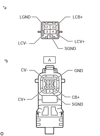
| *a | Component without harness connected
(Outer Rear View Mirror Assembly LH) |
| *b | Front view of wire harness connector
(to Side Television Camera Assembly LH) |
Disconnect the outer rear view mirror assembly LH connector.
Disconnect the side television camera assembly LH connector.
Measure the resistance according to the value(s) in the table below.
- Standard Resistance:
Tester Connection Condition Specified Condition 2 (LCB+) - A-4 (CB+) Always Below 1 Ω 4 (LCV+) - A-3 (CV+) Always Below 1 Ω 3 (LCV-) - A-1 (CV-) Always Below 1 Ω 1 (LGND) - A-2 (GND) Always Below 1 Ω 5 (SGND) - A-5 (SGND) Always Below 1 Ω 2 (LCB+) or A-4 (CB+) - Body ground Always 10 kΩ or higher 4 (LCV+) or A-3 (CV+) - Body ground Always 10 kΩ or higher 3 (LCV-) or A-1 (CV-) - Body ground Always 10 kΩ or higher 1 (LGND) or A-2 (GND) - Body ground Always 10 kΩ or higher 5 (SGND) or A-5 (SGND) - Body ground Always 10 kΩ or higher
- Result:
Proceed to OK NG
OK
NG
Replace the side television camera assembly LH with a new or normally functioning one.
Check if the same malfunction reoccurs when the side monitor screen is displayed.
- OK:
Malfunction does not reoccur (returns to normal)
- Result:
Proceed to OK NG
OK
NG
Disconnect the O214 parking assist ECU connector.
Disconnect the K22 outer rear view mirror assembly RH connector.
Measure the resistance according to the value(s) in the table below.
- Standard Resistance:
Tester Connection Condition Specified Condition O214-1 (RCB+) - K22-2 (RCB+) Always Below 1 Ω O214-3 (RCV+) - K22-4 (RCV+) Always Below 1 Ω O214-4 (RCV-) - K22-3 (RCV-) Always Below 1 Ω O214-2 (RGND) - K22-1 (RGND) Always Below 1 Ω O214-5 (SGND) - K22-5 (SGND) Always Below 1 Ω O214-1 (RCB+) or K22-2 (RCB+) - Body ground Always 10 kΩ or higher O214-3 (RCV+) or K22-4 (RCV+) - Body ground Always 10 kΩ or higher O214-4 (RCV-) or K22-3 (RCV-) - Body ground Always 10 kΩ or higher O214-2 (RGND) or K22-1 (RGND) - Body ground Always 10 kΩ or higher O214-5 (SGND) or K22-5 (SGND) - Body ground Always 10 kΩ or higher
- Result:
Proceed to OK NG
OK
NG
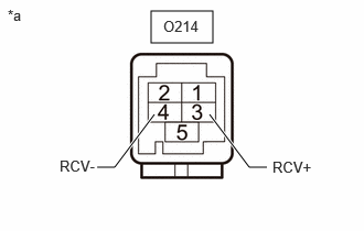
| *a | Component without harness connected
(Parking Assist ECU) |
Disconnect the O214 parking assist ECU connector.
Measure the resistance according to the value(s) in the table below.
- Standard Resistance:
Tester Connection Condition Specified Condition O214-3 (RCV+) - Body ground Always 10 kΩ or higher O214-4 (RCV-) - Body ground Always 10 kΩ or higher
- Result:
Proceed to OK NG
OK
NG
Disconnect the K22 outer rear view mirror assembly RH connector.
Measure the resistance according to the value(s) in the table below.
- Standard Resistance:
Tester Connection Condition Specified Condition K22-1 (RGND) - Body ground Always Below 1 Ω
Measure the voltage according to the value(s) in the table below.
- Standard Voltage:
Tester Connection Switch Condition Specified Condition K22-2 (RCB+) - K22-1 (RGND) Ignition switch ON 7.5 to 8.5 V
- Result:
Proceed to OK NG
OK
NG
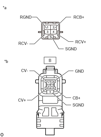
| *a | Component without harness connected
(Outer Rear View Mirror Assembly RH) |
| *b | Front view of wire harness connector
(to Side Television Camera Assembly RH) |
Disconnect the side television camera assembly RH connector.
Disconnect the outer rear view mirror assembly RH connector.
Measure the resistance according to the value(s) in the table below.
- Standard Resistance:
Tester Connection Condition Specified Condition 2 (RCB+) - B-4 (CB+) Always Below 1 Ω 4 (RCV+) - B-3 (CV+) Always Below 1 Ω 3 (RCV-) - B-1 (CV-) Always Below 1 Ω 1 (RGND) - B-2 (GND) Always Below 1 Ω 5 (SGND) - B-5 (SGND) Always 10 kΩ or higher 2 (RCB+) or B-4 (CB+) - Body ground Always 10 kΩ or higher 4 (RCV+) or B-3 (CV+) - Body ground Always 10 kΩ or higher 3 (RCV-) or B-1 (CV-) - Body ground Always 10 kΩ or higher 1 (RGND) or B-2 (GND) - Body ground Always 10 kΩ or higher 5 (SGND) or B-5 (SGND) - Body ground Always 10 kΩ or higher
- Result:
Proceed to OK NG
OK
NG
Replace the side television camera assembly RH with a new or normally functioning one.
Check if the same malfunction reoccurs when the side monitor screen is displayed.
- OK:
Malfunction does not reoccur (returns to normal)
- Result:
Proceed to OK NG
OK
NG
Disconnect the O206 parking assist ECU connector.
Disconnect the I253 radio and display receiver assembly connector.
Measure the resistance according to the value(s) in the table below.
- Standard Resistance:
Tester Connection Condition Specified Condition O206-10 (RSW+) - I253-19 (CSW) Always Below 1 Ω O206-10 (RSW+) or I253-19 (CSW) - Body ground Always 10 kΩ or higher
- Result:
Proceed to OK NG
OK
NG
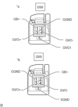
| *a | Front side of GVIF signal line connector
(to Parking Assist ECU) |
| *b | Front side of GVIF signal line connector
(to Radio and Display Receiver Assembly) |
Disconnect the I268 parking assist ECU connector.
Disconnect the I269 radio and display receiver assembly connector.
Measure the resistance according to the value(s) in the table below.
- Standard Resistance:
Tester Connection Condition Specified Condition I268-1 (GB+) - I269-2 (GB+) Always Below 1 Ω I268-3 (GVO+) - I269-3 (GVO+) Always Below 1 Ω I268-4 (GVO-) - I269-4 (GVO-) Always Below 1 Ω I268-2 (GGND) - I269-1 (GGND) Always Below 1 Ω I268-5 (GVG1) - I269-5 (SGND) Always Below 1 Ω I268-1 (GB+) or I269-2 (GB+) - Body ground Always 10 kΩ or higher I268-3 (GVO+) or I269-3 (GVO+) - Body ground Always 10 kΩ or higher I268-4 (GVO-) or I269-4 (GVO-) - Body ground Always 10 kΩ or higher I268-2 (GGND) or I269-1 (GGND) - Body ground Always 10 kΩ or higher I268-5(GVG1) or I269-5(SGND) - Body ground Always 10 kΩ or higher
- Result:
Proceed to OK NG
OK
NG
Replace the GVIF cable with a new or normally functioning one.
Check if the same malfunction reoccurs when the panoramic view monitor screen is displayed.
- OK:
Malfunction does not reoccur (returns to normal).
- Result:
Proceed to OK NG
OK
NG
Replace the radio and display receiver assembly with a new or normally functioning one.
Check if the same malfunction reoccurs when the panoramic view monitor screen is displayed.
- OK:
Malfunction does not reoccur (returns to normal).
- Result:
Proceed to OK NG
OK
NG
One by one in order, repeatedly disconnect then reconnect the O212, O213, O215, and O214 parking assist ECU connector. When disconnected, check the camera image for a black screen or distortion.
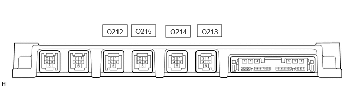
- Result:
Result Proceed to When connector O212 is disconnected, only the rear camera image is black or distorted A When connector O213 is disconnected, only the front camera image is black or distorted B When connector O215 is disconnected, only the left-side camera image is black or distorted C When connector O214 is disconnected, only the right-side camera image is black or distorted D Other than above E
A
B
C
D
E