PARK ASSIST / MONITORING PANORAMIC VIEW MONITOR SYSTEM(Production Date from 2023/04) CALIBRATION
ADJUST PANORAMIC VIEW MONITOR SYSTEM
- NOTICE:
- ·
If any of the work in the following table has been performed, perform registration of the panoramic view monitor system.
·Work performed during servicing may require the registration and initialization of the panoramic view monitor system and other systems.
·Conduct the pre-work checks (Procedure 1) before performing screen adjustment.
Part Name Operation Adjustment Item Proceed to Parking assist ECU Replacement Import/Export constant value Procedure 10
·When ECU data writing completes normally, the following procedure is not necessary.
·When ECU data writing does not complete normally, perform the following procedure.
Procedure 2 Procedure 7*1 Procedure 8*2 Procedure 9 Suspension, tires, etc. The vehicle height changes because of suspension or tire replacement Parking assist ECU initialization Procedure 2 Procedure 7*1 Procedure 8*2 Procedure 9 ·Front television camera assembly
·Front bumper assembly
·Radiator grille assembly*3
·Replacement
·Installation angle of the front television camera changes because of the removal and installation of the front television camera, etc.
Front television camera view adjustment Procedure 2 Procedure 3*1 Procedure 8*2 Procedure 9 Rear television camera assembly ·Replacement
·Installation angle of the television camera changes because of the removal and installation of the television camera, etc.
Rear television camera view adjustment Procedure 2 Procedure 4*1 Procedure 8*2 Procedure 9 ·Side television camera assembly LH
·Outer rear view mirror assembly LH
·Replacement
·Installation angle of the side television camera changes because of the removal and installation of the side television camera, etc.
Side television camera view adjustment Procedure 2 Procedure 5*1 Procedure 8*2 Procedure 9 ·Side television camera assembly RH
·Outer rear view mirror assembly RH
·Replacement
·Installation angle of the side television camera changes because of the removal and installation of the side television camera, etc.
Side television camera view adjustment Procedure 2 Procedure 6*1 Procedure 8*2 Procedure 9 ·Front television camera assembly, radiator grille assembly*3 or front bumper assembly
·Rear television camera assembly
·Side television camera assembly LH or outer rear view mirror assembly LH
·Side television camera assembly RH or outer rear view mirror assembly RH
Replacement or removal and installation of 2 or more parts Television camera view adjustment Procedure 2 Procedure 7*1 Procedure 8*2 Procedure 9
*1: At the time of SST (marker tool set) non-use
*2: At the time of use SST (marker tool set)
*3: for TFTM Made
PROCEDURE 1: PRE-WORK CHECKS
Preliminary checks
- NOTICE:
- ·
Provide shadow to prevent backlight from hitting the camera.
·Use string that does not stretch.
·Apply pieces of adhesive tape to serve as check markers. When placing the markers, make them 100 mm (3.94 in.) wide.
Perform the work in a wide, level location.
Forward/rearward of the vehicle: Approximately 1.3 m each end
Left/right of the vehicle: Approximately 1.2 m each side
Park the vehicle on a flat surface with the steering wheel centered.
- NOTICE:
-
Before stopping the vehicle, move the vehicle backward and forward to ensure that both the steering wheel and the tires point straight ahead.
Adjust the tire pressure to the specified value(s).
Remove all luggage from the vehicle and place the markers before starting work.
Marker locations
Secure the strings and markers to the location required to make the checks as shown in the illustration.
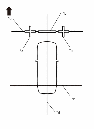
| *a | Cross Check Marker |
| *b | Check Marker |
| *c | String 1 |
| *d | String 2 |
| *e | String 3 |

|
Front of Vehicle |
When adjusting front camera only
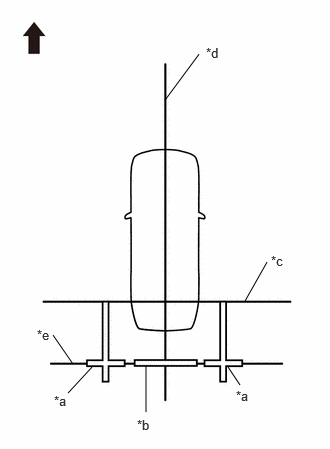
| *a | Cross Check Marker |
| *b | Check Marker |
| *c | String 1 |
| *d | String 2 |
| *e | String 4 |
|
|
Front of Vehicle |
When adjusting rear camera only
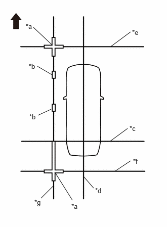
| *a | Cross Check Marker |
| *b | Check Marker |
| *c | String 1 |
| *d | String 2 |
| *e | String 3 |
| *f | String 4 |
| *g | String 5 |
|
|
Front of Vehicle |
When adjusting side camera LH only
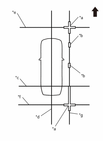
| *a | Cross Check Marker |
| *b | Check Marker |
| *c | String 1 |
| *d | String 2 |
| *e | String 3 |
| *f | String 4 |
| *g | String 6 |
|
|
Front of Vehicle |
When adjusting side camera RH only
When adjusting all cameras
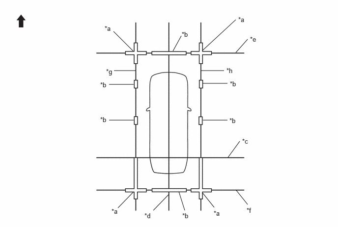
| *a | Cross Check Marker | *b | Check Marker |
| *c | String 1 | *d | String 2 |
| *e | String 3 | *f | String 4 |
| *g | String 5 | *h | String 6 |
|
|
Front of Vehicle | - | - |
Marker positions
Set the target bars in the positions shown in the illustration.
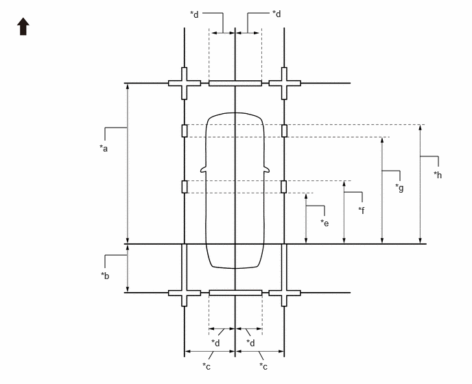
| *a | 4800 mm (15.74 ft.) | *b | 1200 mm (3.94 ft.) |
| *c | 1500 mm (4.92 ft.) | *d | 693 mm (2.27 ft.) |
| *e | 1500 mm (4.92 ft.) | *f | 1700 mm (5.58 ft.) |
| *g | 2900 mm (9.51 ft.) | *h | 3100 mm (10.17 ft.) |
|
|
Front of Vehicle | - | - |
PROCEDURE 2: SET DATUM POINTS
Extend the datum line [string (1)].
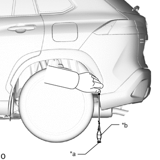
| *a | Mark A |
| *b | Weight |
Hang a weight with a pointed tip at the position shown in the illustration and accurately mark the center position on the road surface. (Mark A)
- NOTICE:
-
Observe the string to check that the weight hangs straight down.
Repeat the procedure to mark the right side. (Mark B)
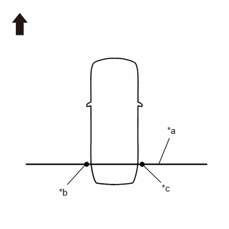
| *a | String 1 |
| *b | Mark A |
| *c | Mark B |
|
|
Front of Vehicle |
Secure string (1) to pass through marks A and B at the left and right sides.
- NOTICE:
- ·
When securing the string, check that there is no slack and the string is not twisted.
·Extend the line for approximately 0.4 m or more from the left/right side of the vehicle.
Extend the vehicle center line [string (2)].
Hang a weight with a pointed tip such that is passes through the center of the front emblem and accurately mark the center position on the road surface. (Mark C)

| *a | Center | *b | Weight |
| *c | String | *d | Mark C |
| *e | Bilateral Symmetry | - | - |
Hang a weight with a pointed tip so that it passes through the center of the rear emblem and accurately mark the center position on the road surface. (Mark D)
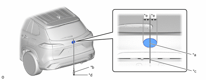
| *a | Center | *b | Weight |
| *c | String | *d | Mark D |
| *e | Bilateral Symmetry | - | - |
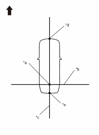
| *a | Datum Point |
| *b | String 1 |
| *c | String 2 |
| *d | Mark C |
| *e | Mark D |
|
|
Front of Vehicle |
Secure string (2) to pass through marks C and D at the front and rear of the vehicle.
- NOTICE:
-
When securing the string, check that there is no slack and the string is not twisted.
- HINT:
-
Set the point where strings 1 and 2 intersect as the datum point.
PROCEDURE 3: SET MARKERS (FRONT ADJUSTMENT)
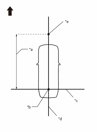
| *a | 4800 mm (15.74 ft.) |
| *b | Datum Point |
| *c | String 1 |
| *d | String 2 |
| *e | Mark E |
|
|
Front of Vehicle |
In front of the vehicle, extend string (3) perpendicular to the vehicle center line [string (2)], and place a marker.
Mark a position on string (2) in front of the vehicle, 4800 mm (15.74 ft.) from the datum point. (Mark E)
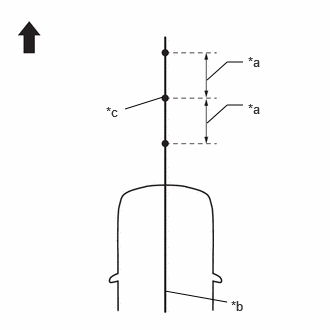
| *a | 400 mm (1.31 ft.) |
| *b | String 2 |
| *c | Mark E |
|
|
Front of Vehicle |
Fix the ends of 2 strings (800 mm [2.62 ft.] long) at 2 positions 400 mm (1.31 ft.) from mark E as shown in the illustration.
Move the free ends of the 2 strings and mark the point where the ends meet. (Marks F and G)
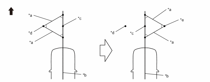
| *a | 800 mm (2.62 ft.) String | *b | String 2 |
| *c | Mark E | *d | Mark F |
| *e | Mark G | - | - |
|
|
Front of Vehicle | - | - |
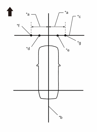
| *a | 1500 mm (4.92 ft.) |
| *b | String 2 |
| *c | String 3 |
| *d | Mark F |
| *e | Mark G |
| *f | Mark H |
| *g | Mark I |
|
|
Front of Vehicle |
Secure string (3) to pass through marks F and G as shown in the illustration.
- NOTICE:
-
When securing the string, check that there is no slack and the string is not twisted.
Make a mark on string (3), 1500 mm (4.92 ft.) to the left and right of the vehicle center line (string (2)). (Marks H and I)
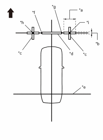
| *a | 800 mm (2.62 ft.) |
| *b | 100 mm (0.33 ft.) |
| *c | Cross Check Marker |
| *d | Check Marker |
| *e | String 1 |
| *f | Mark F |
| *g | Mark G |
| *h | Mark H |
| *i | Mark I |
|
|
Front of Vehicle |
Place and secure the cross target bars, centered on marks H and I as shown in the illustration.
- NOTICE:
- ·
Place the cross check markers perpendicular to the string.
·Make each arm of the cross check markers 800 mm (2.62 ft.) long and 100 mm (0.33 ft.) wide.
Place the target bar between marks F and G.
Perform the screen adjustment procedure (procedure 9).
PROCEDURE 4: SET MARKERS (REAR ADJUSTMENT)
To the rear of the vehicle, extend string (4) perpendicular to the vehicle center line [string (2)], and place a check marker.
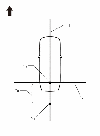
| *a | 1200 mm (3.94 ft.) |
| *b | Datum Point |
| *c | String 1 |
| *d | String 2 |
| *e | Mark J |
|
|
Front of Vehicle |
Mark a position on string (2) to the rear of the vehicle, 1200 mm (3.94 ft.) from the datum point. (Mark J)
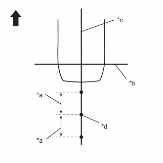
| *a | 400 mm (1.31 ft.) |
| *b | String 1 |
| *c | String 2 |
| *d | Mark J |
|
|
Front of Vehicle |
Fix the ends of two 800 mm (2.62 ft.) strings at two positions 400 mm (1.31 ft.) from mark J as shown in the illustration.
Move the free ends of the 2 strings and mark the point where the ends meet. (Marks K and L)
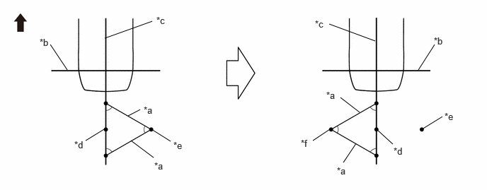
| *a | 800 mm (2.62 ft.) String | *b | String 1 |
| *c | String 2 | *d | Mark J |
| *e | Mark K | *f | Mark L |
|
|
Front of Vehicle | - | - |
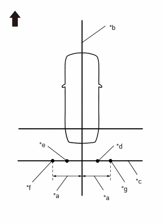
| *a | 1500 mm (4.92 ft.) |
| *b | String 2 |
| *c | String 4 |
| *d | Mark K |
| *e | Mark L |
| *f | Mark M |
| *g | Mark N |
|
|
Front of Vehicle |
Secure string (4) to pass through marks K and L as shown in the illustration.
- NOTICE:
-
When securing the string, check that there is no slack and the string is not twisted.
Make a mark on string (4), 1500 mm (4.92 ft.) to the left and right of the vehicle center line [string (2)].
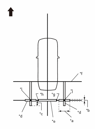
| *a | 800 mm (2.62 ft.) |
| *b | 100 mm (0.33 ft.) |
| *c | 400 mm (1.31 ft.) |
| *d | Cross Check Marker |
| *e | Check Marker |
| *f | String 1 |
| *g | Mark K |
| *h | Mark L |
| *i | Mark M |
| *j | Mark N |
|
|
Front of Vehicle |
Place and secure the cross target bars, centered on marks M and N as shown in the illustration.
- NOTICE:
- ·
Place the cross check markers perpendicular to the string.
·Make each arm of the cross check markers 800 mm (2.62 ft.) long and 100 mm (0.33 ft.) wide.
·Extend the rear cross target bars to string (1) as shown in the illustration.
Place the target bar between marks K and L.
Perform the screen adjustment procedure (procedure 9).
PROCEDURE 5: SET MARKERS (LEFT-SIDE ADJUSTMENT)
At the left side of the vehicle, extend [string (5)] parallel to the vehicle center line [string (2)], and place a marker.
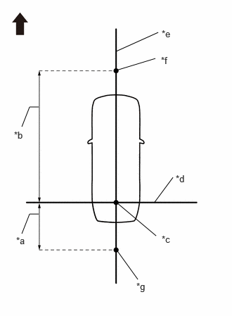
| *a | 1200 mm (3.94 ft.) |
| *b | 4800 mm (15.74 ft.) |
| *c | Datum Point |
| *d | String 1 |
| *e | String 2 |
| *f | Mark E |
| *g | Mark J |
|
|
Front of Vehicle |
Mark a position on string (2) in front of the vehicle, 4800 mm (15.74 ft.) from the datum point. (Mark E)
Mark a position on string (2) to the rear of the vehicle, 1200 mm (3.94 ft.) from the datum point. (Mark J)
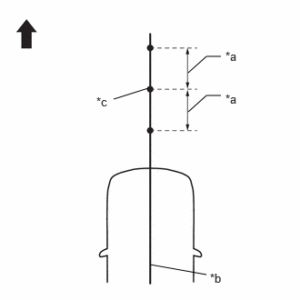
| *a | 400 mm (1.31 ft.) |
| *b | String 2 |
| *c | Mark E |
|
|
Front of Vehicle |
Fix the ends of 2 strings (800 mm [2.62 ft.] long) at 2 positions 400 mm (1.31 ft.) from mark E as shown in the illustration.
Move the free ends of the 2 strings and mark the point where the ends meet. (Marks F and G)
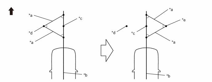
| *a | 800 mm (2.62 ft.) String | *b | String 2 |
| *c | Mark E | *d | Mark F |
| *e | Mark G | - | - |
|
|
Front of Vehicle | - | - |
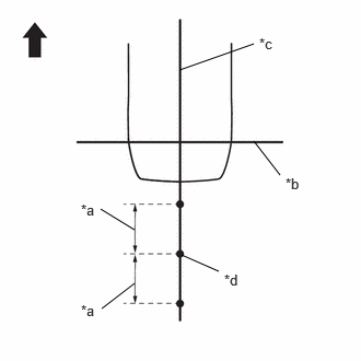
| *a | 400 mm (1.31 ft.) |
| *b | String 1 |
| *c | String 2 |
| *d | Mark J |
|
|
Front of Vehicle |
Fix the ends of two 800 mm (2.62 ft.) strings at two positions 400 mm (1.31 ft.) from mark J as shown in the illustration.
Move the free ends of the 2 strings and mark the point where the ends meet. (Marks K and L)
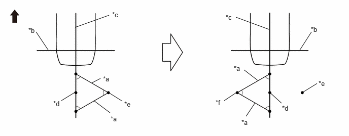
| *a | 800 mm (2.62 ft.) String | *b | String 1 |
| *c | String 2 | *d | Mark J |
| *e | Mark K | *f | Mark L |
|
|
Front of Vehicle | - | - |
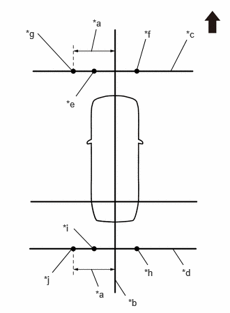
| *a | 1500 mm (4.92 ft.) |
| *b | String 2 |
| *c | String 3 |
| *d | String 4 |
| *e | Mark F |
| *f | Mark G |
| *g | Mark H |
| *h | Mark K |
| *i | Mark L |
| *j | Mark M |
|
|
Front of Vehicle |
Secure strings (3) and (4) to pass through marks F and G and marks K and L, respectively as shown in the illustration.
- NOTICE:
-
When securing the string, check that there is no slack and the string is not twisted.
Mark strings 3 and 4, 1500 mm (4.92 ft.) to the left of the vehicle center line (string 2). (Marks H and M)
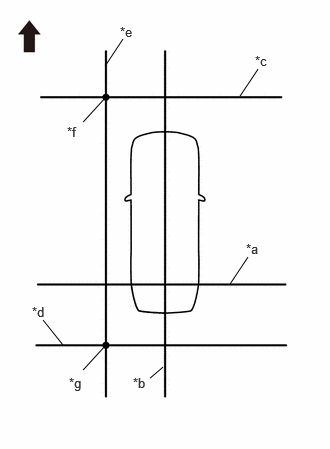
| *a | String 1 |
| *b | String 2 |
| *c | String 3 |
| *d | String 4 |
| *e | String 5 |
| *f | Mark H |
| *g | Mark M |
|
|
Front of Vehicle |
Secure string (5) to pass through marks H and M as shown in the illustration.
- NOTICE:
-
When securing the string, check that there is no slack and the string is not twisted.
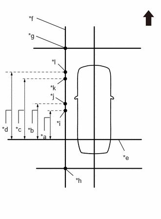
| *a | 1500 mm (4.92 ft.) |
| *b | 1700 mm (5.58 ft.) |
| *c | 2900 mm (9.51 ft.) |
| *d | 3100 mm (10.17 ft.) |
| *e | String 1 |
| *f | String 5 |
| *g | Mark H |
| *h | Mark M |
| *i | Mark O |
| *j | Mark P |
| *k | Mark Q |
| *l | Mark R |
|
|
Front of Vehicle |
Make marks on string 5 that are 1500 mm (4.92 ft.), 1700 mm (5.58 ft.), 2900 mm (9.51 ft.) and 3100 mm (10.17 ft.) from the datum line (string 1) as shown in the illustration. (Marks O, P, Q and R)
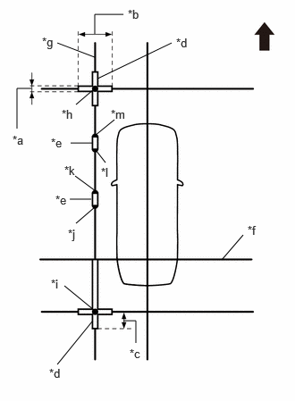
| *a | 100 mm (0.33 ft.) |
| *b | 800 mm (2.62 ft.) |
| *c | 400 mm (1.31 ft.) |
| *d | Cross Check Marker |
| *e | Check Marker |
| *f | String 1 |
| *g | String 5 |
| *h | Mark H |
| *i | Mark M |
| *j | Mark O |
| *k | Mark P |
| *l | Mark Q |
| *m | Mark R |
|
|
Front of Vehicle |
Place and secure the cross target bars, centered on marks H and M as shown in the illustration.
- NOTICE:
- ·
Place the cross check markers perpendicular to the string.
·Make each arm of the cross check markers 800 mm (2.62 ft.) long and 100 mm (0.33 ft.) wide.
·Extend the rear cross target bars to string (1) as shown in the illustration.
Place target bar between marks O and P and marks Q and R.
Perform the screen adjustment procedure (procedure 9).
PROCEDURE 6: SET MARKERS (RIGHT-SIDE ADJUSTMENT)
At the right side of the vehicle, extend [string (6)] parallel to the vehicle center line [string (2)], and place a marker.
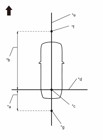
| *a | 1200 mm (3.94 ft.) |
| *b | 4800 mm (15.74 ft.) |
| *c | Datum Point |
| *d | String 1 |
| *e | String 2 |
| *f | Mark E |
| *g | Mark J |
|
|
Front of Vehicle |
Mark a position on string (2) in front of the vehicle, 4800 mm (15.74 ft.) from the datum point. (Mark E)
Mark a position on string (2) to the rear of the vehicle, 1200 mm (3.94 ft.) from the datum point. (Mark J)
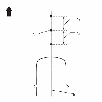
| *a | 400 mm (1.31 ft.) |
| *b | String 2 |
| *c | Mark E |
|
|
Front of Vehicle |
Fix the ends of 2 strings (800 mm [2.62 ft.] long) at 2 positions 400 mm (1 .31 ft.) from mark E as shown in the illustration.
Move the free ends of the 2 strings and mark the point where the ends meet. (Marks F and G)
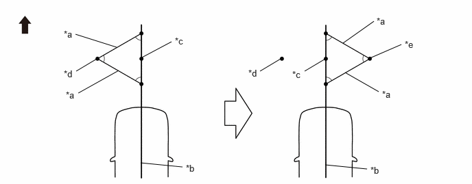
| *a | 800 mm (2.62 ft.) String | *b | String 2 |
| *c | Mark E | *d | Mark F |
| *e | Mark G | - | - |
|
|
Front of Vehicle | - | - |
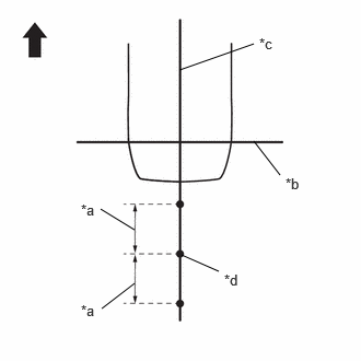
| *a | 400 mm (1.31 ft.) |
| *b | String 1 |
| *c | String 2 |
| *d | Mark J |
|
|
Front of Vehicle |
Fix the ends of two 800 mm (2.62 ft.) strings at two positions 400 mm (1.31 ft.) from mark J as shown in the illustration.
Move the free ends of the 2 strings and mark the point where the ends meet. (Marks K and L)
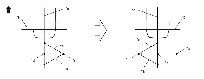
| *a | 800 mm (2.62 ft.) String | *b | String 1 |
| *c | String 2 | *d | Mark J |
| *e | Mark K | *f | Mark L |
|
|
Front of Vehicle | - | - |
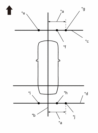
| *a | 1500 mm (4.92 ft.) |
| *b | String 2 |
| *c | String 3 |
| *d | String 4 |
| *e | Mark F |
| *f | Mark G |
| *g | Mark I |
| *h | Mark K |
| *i | Mark L |
| *j | Mark N |
|
|
Front of Vehicle |
Secure strings (3) and (4) to pass through marks F and G and marks K and L, respectively as shown in the illustration.
- NOTICE:
-
When securing the string, check that there is no slack and the string is not twisted.
Mark positions on strings 3 and 4, 1500 mm (4.92 ft.) to the right of the vehicle center line (string 2). (Marks I and N)
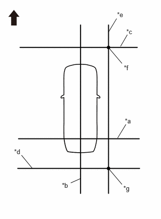
| *a | String 1 |
| *b | String 2 |
| *c | String 3 |
| *d | String 4 |
| *e | String 6 |
| *f | Mark I |
| *g | Mark N |
|
|
Front of Vehicle |
Secure string (6) to pass through marks I and N as shown in the illustration.
- NOTICE:
-
When securing the string, check that there is no slack and the string is not twisted.
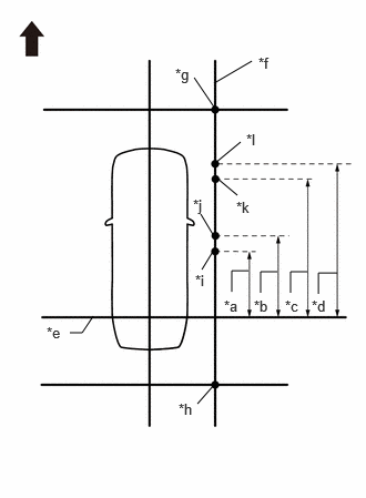
| *a | 1500 mm (4.92 ft.) |
| *b | 1700 mm (5.58 ft.) |
| *c | 2900 mm (9.51 ft.) |
| *d | 3100 mm (10.17 ft.) |
| *e | String 1 |
| *f | String 6 |
| *g | Mark I |
| *h | Mark N |
| *i | Mark S |
| *j | Mark T |
| *k | Mark U |
| *l | Mark V |
|
|
Front of Vehicle |
Make marks on string 6 that are 1500 mm (4.92 ft.), 1700 mm (5.58 ft.), 2900 mm (9.51 ft.), and 3100 mm (10.17 ft.) from the datum line (string 1) as shown in the illustration. (Marks S, T, U and V)
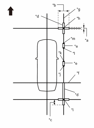
| *a | 100 mm (0.33 ft.) |
| *b | 800 mm (2.62 ft.) |
| *c | 400 mm (1.31 ft.) |
| *d | Cross Check Marker |
| *e | Check Marker |
| *f | String 1 |
| *g | String 6 |
| *h | Mark I |
| *i | Mark N |
| *j | Mark S |
| *k | Mark T |
| *l | Mark U |
| *m | Mark V |
|
|
Front of Vehicle |
Place and secure the cross target bars centered on marks I and N as shown in the illustration.
- NOTICE:
- ·
Place the cross check markers perpendicular to the string.
·Make each arm of the cross check markers 800 mm (2.62 ft.) long and 100 mm (0.33 ft.) wide.
·Extend the rear cross target bars to string (1) as shown in the illustration.
Place the check markers between marks S and T, and marks U and V.
Perform the screen adjustment procedure (procedure 9).
PROCEDURE 7: SET MARKERS (ADJUSTMENT OF ALL CAMERAS)
At the right and left sides of the vehicle, extend strings (5) and (6) parallel to the vehicle center line [string (2)], and place markers.
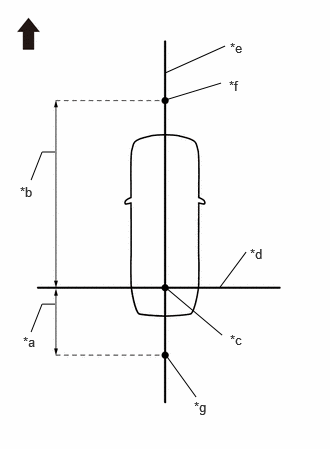
| *a | 1200 mm (3.94 ft.) |
| *b | 4500 mm (14.76 ft.) |
| *c | Datum Point |
| *d | String 1 |
| *e | String 2 |
| *f | Mark E |
| *g | Mark J |
|
|
Front of Vehicle |
Mark a position on string (2) in front of the vehicle, 4800 mm (15.74 ft.) from the datum point. (Mark E)
Mark a position on string (2) to the rear of the vehicle, 1200 mm (3.94 ft.) from the datum point. (Mark J)
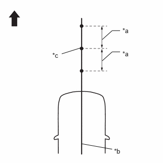
| *a | 400 mm (1.31 ft.) |
| *b | String 2 |
| *c | Mark E |
|
|
Front of Vehicle |
Fix the ends of 2 strings (800 mm [2.62 ft.] long) at 2 positions 400 mm (1.31 ft.) from mark E as shown in the illustration.
Move the free ends of the 2 strings and mark the point where the ends meet. (Marks F and G)
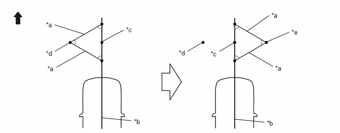
| *a | 800 mm (2.62 ft.) String | *b | String 2 |
| *c | Mark E | *d | Mark F |
| *e | Mark G | - | - |
|
|
Front of Vehicle | - | - |
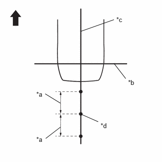
| *a | 400 mm (1.31 ft.) |
| *b | String 1 |
| *c | String 2 |
| *d | Mark J |
|
|
Front of Vehicle |
Fix the ends of two 800 mm (2.62 ft.) strings at two positions 400 mm (1.31 ft.) from mark J as shown in the illustration.
Move the free ends of the 2 strings and mark the point where the ends meet. (Marks K and L)
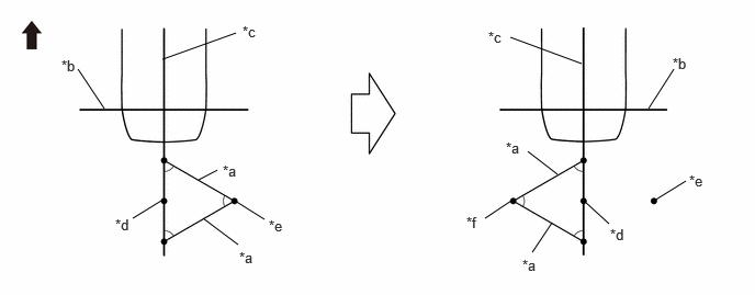
| *a | 800 mm (2.62 ft.) String | *b | String 1 |
| *c | String 2 | *d | Mark J |
| *e | Mark K | *f | Mark L |
|
|
Front of Vehicle | - | - |
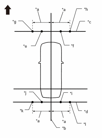
| *a | 1500 mm (4.92 ft.) |
| *b | String 2 |
| *c | String 3 |
| *d | String 4 |
| *e | Mark F |
| *f | Mark G |
| *g | Mark H |
| *h | Mark I |
| *i | Mark K |
| *j | Mark L |
| *k | Mark M |
| *l | Mark N |
|
|
Front of Vehicle |
Secure strings (3) and (4) to pass through marks F and G and marks K and L, respectively as shown in the illustration.
- NOTICE:
-
When securing the string, check that there is no slack and the string is not twisted.
Make a mark on string (3), 1500 mm (4.92 ft.) to the left and right of the vehicle center line [string (2)]. (Marks H and I)
Make a mark on string (4), 1500 mm (4.92 ft.) to the left and right of the vehicle center line [string (2)]. (Marks M and N)
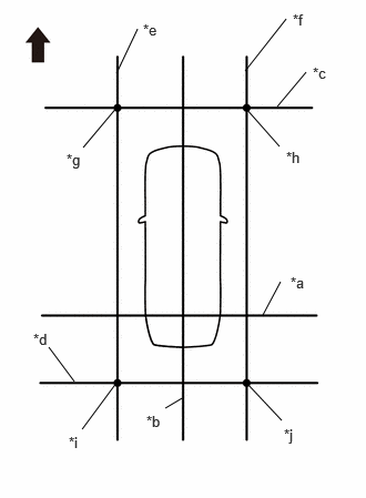
| *a | String 1 |
| *b | String 2 |
| *c | String 3 |
| *d | String 4 |
| *e | String 5 |
| *f | String 6 |
| *g | Mark H |
| *h | Mark I |
| *i | Mark M |
| *j | Mark N |
|
|
Front of Vehicle |
Secure strings (5) and (6) to pass through marks H and M and marks I and N, respectively as shown in the illustration.
- NOTICE:
-
When securing the string, check that there is no slack and the string is not twisted.
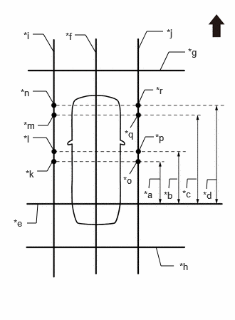
| *a | 1500 mm (4.92 ft.) |
| *b | 1700 mm (5.58 ft.) |
| *c | 2900 mm (9.51 ft.) |
| *d | 3100 mm (10.17 ft.) |
| *e | String 1 |
| *f | String 2 |
| *g | String 3 |
| *h | String 4 |
| *i | String 5 |
| *j | String 6 |
| *k | Mark O |
| *l | Mark P |
| *m | Mark Q |
| *n | Mark R |
| *o | Mark S |
| *p | Mark T |
| *q | Mark U |
| *r | Mark V |
|
|
Front of Vehicle |
Make marks on string 5 that are 1500 mm (4.92 ft.), 1700 mm (5.58 ft.), 2900 mm (9.51 ft.), and 3100 mm (10.17 ft.) from the datum line (string 1) as shown in the illustration. (Marks O, P, Q and R)
Make marks on string 6 that are 1500 mm (4.92 ft.), 1700 mm (5.58 ft.), 2900 mm (9.51 ft.), and 3100 mm (10.17 ft.) from the datum line (string 1) as shown in the illustration. (Marks S, T, U and V)
Place and secure the cross target bars centered on marks H and I and marks M and N as shown in the illustration.
- NOTICE:
- ·
Place the cross check markers perpendicular to the string.
·Make each arm of the cross check markers 800 mm long and 100 mm wide.
·Extend the rear cross target bars to string (1) as shown in the illustration.
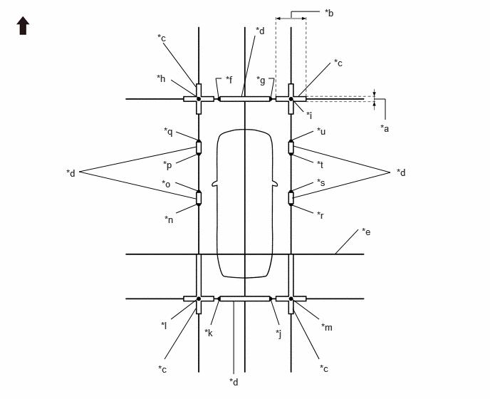
| *a | 100 mm (0.33 ft.) | *b | 800 mm (2.62 ft.) |
| *c | Cross Check Marker | *d | Check Marker |
| *e | String 1 | *f | Mark F |
| *g | Mark G | *h | Mark H |
| *i | Mark I | *j | Mark K |
| *k | Mark L | *l | Mark M |
| *m | Mark N | *n | Mark O |
| *o | Mark P | *p | Mark Q |
| *q | Mark R | *r | Mark S |
| *s | Mark T | *t | Mark U |
| *u | Mark V | - | - |
|
|
Front of Vehicle | - | - |
Place target bars between marks F and G, marks K and L, marks O and P, marks Q and R, marks S and T, and marks U and V.
Perform the screen adjustment procedure (procedure 9).
PROCEDURE 8: SET MARKERS (SST ADJUSTMENT)
Using SST (marker tool set), place the markers.
- SST
- 09870-30010
| Part Name | Color | Length | Qty |
|---|---|---|---|
| Marker A | White | 800 mm (31.5 in.) | 6 |
| Marker B | White | 950 mm (37.4 in.) | 2 |
| Marker E | White | 350 mm (13.8 in.) | 6 |
| Marker F | White | 1000 mm (39.4 in.) | 2 |
| Marker G | White | 293 mm (11.5 in.) | 4 |
| Marker H | White | 200 mm (7.87 in.) | 4 |
| Spacer J | Black | 1000 mm (39.4 in.) | 6 |
| Spacer K | Black | 500 mm (19.7 in.) | 2 |
| Spacer M | Black | 307 mm (12.1 in.) | 4 |
| Spacer O | Black | 100 mm (3.9 in.) | 6 |
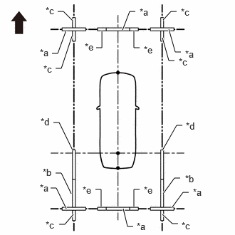
| *a | Marker A |
| *b | Marker B |
| *c | Marker E |
| *d | Marker F |
| *e | Marker G |
|
|
Front of Vehicle |
Set the marker A, marker B, marker E, marker F and marker G so as to surround the vehicle as shown in the illustration.
| Part Name | Color | Length | Qty |
|---|---|---|---|
| Marker A | White | 800 mm (31.5 in.) | 6 |
| Marker B | White | 950 mm (37.4 in.) | 2 |
| Marker E | White | 350 mm (13.8 in.) | 6 |
| Marker F | White | 1000 mm (39.4 in.) | 2 |
| Marker G | White | 293 mm (11.5 in.) | 4 |
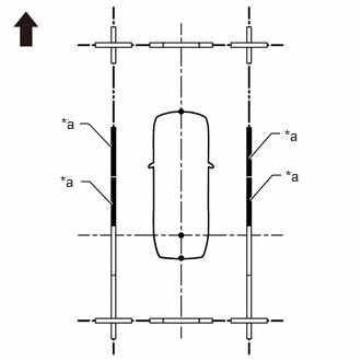
| *a | Spacer J |
|
|
Front of Vehicle |
Set the spacer J as shown in the illustration.
| Part Name | Color | Length | Qty |
|---|---|---|---|
| Spacer J | Black | 1000 mm (39.4 in.) | 4 |
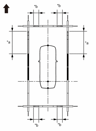
| *a | A |
| *b | B |
|
|
Front of Vehicle |
Combine with spacers and set at positions A and B to assemble the marker tool set.
| Part Name | Color | Length | Qty |
|---|---|---|---|
| Spacer J | Black | 1000 mm (39.4 in.) | 1 |
| Spacer K | Black | 500 mm (19.7 in.) | 1 |
| Spacer O | Black | 100 mm (3.9 in.) | 1 |
- HINT:
-
Create 2 sets and combine together.
| Part Name | Color | Length | Qty |
|---|---|---|---|
| Spacer M | Black | 307 mm (12.1 in.) | 2 |
| Spacer O | Black | 100 mm (3.9 in.) | 2 |
- HINT:
-
Create 4 sets and combine together.
Set the marker H.
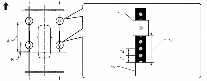
| *a | 100 mm (3.94 in.) | *b | Marker F |
| *c | Marker H | *d | Distance from the front end of the marker F to the rear end of the marker H |
|
|
Front of Vehicle | - | - |
| Marker H Setting Positions | Distance from the front end of the marker F to the rear end of the marker H |
|---|---|
| A | 2100 mm (6.89 ft.) |
| B | 700 mm (2.30 ft.) |
Align the position number on the marker F with the datum line as shown in the illustration.
- NOTICE:
-
When aligning the marker F with the datum line, check that the string used for the datum line is not twisted or bent.
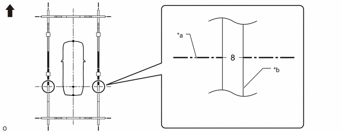
| *a | Datum line | *b | Marker F |
|
|
Front of Vehicle | - | - |
| Marker B Position |
|---|
| 8 |
Align the mark-off line of the marker A set at the front and back with the vehicle center line as shown in the illustration.
- NOTICE:
-
When aligning the marker A with the vehicle center line, check that the string used for the vehicle center line is not twisted or bent.
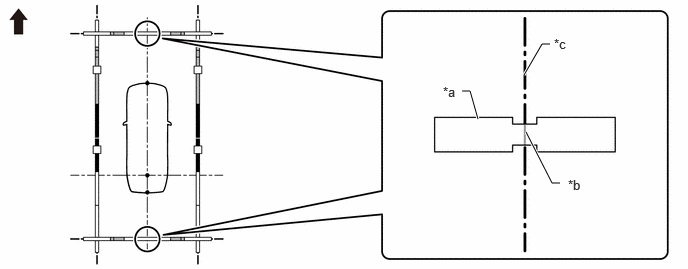
| *a | Marker A | *b | Mark-off line |
| *c | Vehicle center line | - | - |
|
|
Front of Vehicle | - | - |
Check that the entire marker tool set is not distorted after the setting is completed. If there is any distortion, perform corrections so that it is straightened.
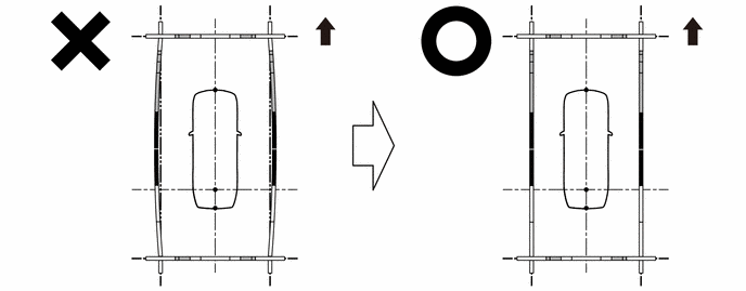
|
|
Front of Vehicle | - | - |
Perform the screen adjustment procedure (procedure 9).
PROCEDURE 9: ADJUST SCREEN
Enter diagnostic mode.
- CAUTION:
-
Adjustment must be performed with start the hybrid control system. Therefore, apply the parking brake, depress the brake pedal and move the shift position to P to ensure that the vehicle does not begin moving unexpectedly.
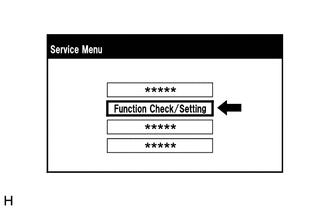
Select "Function Check/Setting" from the Service Menu screen.
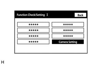
Select "Camera Setting" from the Function Check/Setting I screen to display the Mode Setting(*) screen.
- NOTICE:
-
If "Camera Setting" is not displayed on the screen, turn the ignition switch off, and then turn it ON again and enter the diagnostic mode.
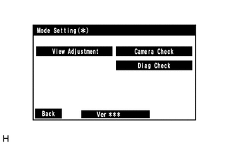
Select "View Adjustment" on the Mode Setting(*) screen to display the Signal Check(*) screen.
- HINT:
-
To select a grayed out item, select and hold the item for 2 seconds or more.
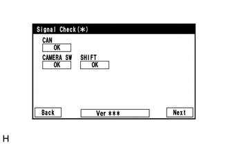
Select "Next" from the Signal Check(*) screen to display the adjustment screen.
- NOTICE:
- ·
When "CHK" (red) is displayed for an item on the Signal Check(*) screen, selecting "Next" will not change to the adjustment screen.
·Check the Signal Check(*) screen when "CHK" (red) is displayed for an item on the Signal Check(*) screen.
Perform screen adjustment.
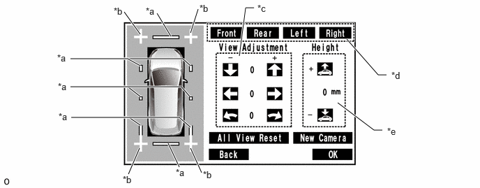
| *a | Red Line | *b | Cross Check Marker (for Connection Judgment) |
| *c | Adjustment Buttons | *d | Camera Select Buttons |
| *e | Vehicle Height Adjustment Buttons | - | - |
- NOTICE:
-
After replacing a camera, use the camera select buttons to select the replaced camera, and select "New Camera".
Check that the cross target bars displayed on the adjustment screen appear connected.
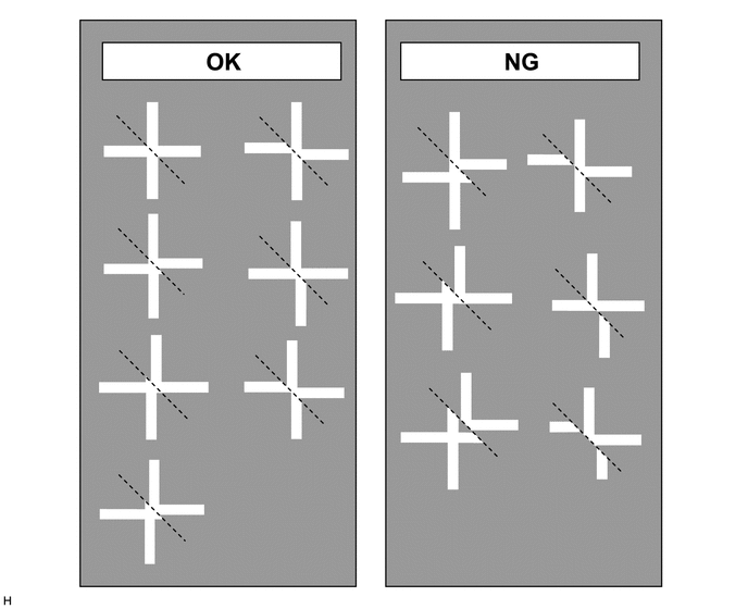
- NOTICE:
- ·
Before checking the markers on the adjustment screen, ensure that the cross target bars have been placed correctly.
·If a cross target bar appears displaced on the adjustment screen, use the camera select buttons to select the corresponding camera, and use the adjustment buttons or vehicle height adjustment buttons to adjust the screen.
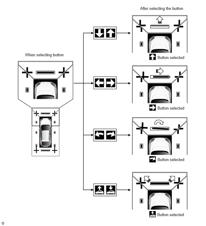 0.875,1.823 2.375,2.031 1.5,0.208 10 false When selecting button 4.875,0.208 6.521,0.417 1.646,0.208 10 false After selecting the button 5.479,1.917 6.51,2.156 1.031,0.24 10 false Button selected 5.479,3.677 6.51,3.917 1.031,0.24 10 false Button selected 5.479,5.469 6.51,5.708 1.031,0.24 10 false Button selected 5.469,7.385 6.5,7.625 1.031,0.24 10 false Button selected
- HINT:
-
To repeat the adjustment, select "All View Reset" to return all adjustment values to their initial values.
Check that the target bars do not protrude outside the red frames displayed on the adjustment screen.
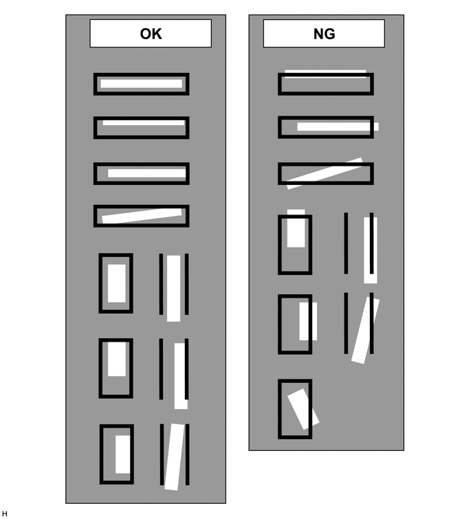
- NOTICE:
- ·
Before checking the adjustment screen, ensure that the check markers have been placed correctly.
·If a target bar protrudes outside a red frame on the adjustment screen, use the camera select buttons to select the corresponding camera, and use the adjustment buttons or vehicle height adjustment buttons to adjust the screen.
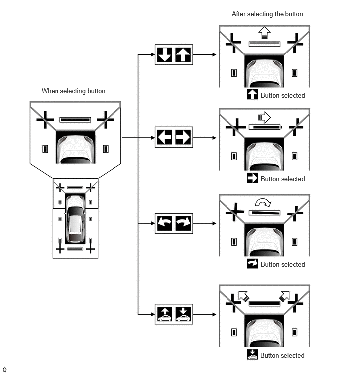 0.875,1.823 2.375,2.031 1.5,0.208 10 false When selecting button 4.875,0.208 6.521,0.417 1.646,0.208 10 false After selecting the button 5.479,1.917 6.51,2.156 1.031,0.24 10 false Button selected 5.479,3.677 6.51,3.917 1.031,0.24 10 false Button selected 5.479,5.469 6.51,5.708 1.031,0.24 10 false Button selected 5.469,7.385 6.5,7.625 1.031,0.24 10 false Button selected
- HINT:
-
To repeat the adjustment, select "All View Reset" to return all adjustment values to their initial values.
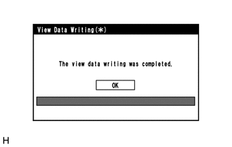
When all adjustments are completed, press "OK".
If data writing ends normally, "The view data writing was completed." is displayed.
Select "OK".
Procedure 10: IMPORT/EXPORT CONSTANT VALUE
- CAUTION:
-
The check must be performed with the ignition switch to ON. Therefore, apply the parking brake, depress the brake pedal and move the shift position to P to ensure that the vehicle does not begin moving unexpectedly.
ECU data save
- HINT:
-
Using the parking assist ECU installed to the vehicle, output the items necessary for camera adjustment.
Using GTS, select "Chassis" → "Circumference Monitoring Camera Control Module" → "Utility" to perform utility.
- Chassis > Circumference Monitoring Camera Control Module > Utility
-
Tester Display ECU Data Save - 50005 470 4656
In accordance with the screen, perform ECU data save.
Procedure After ECU Replacement
Turn the ignition switch to ON, change the shift position to R, and then change the shift position to P.
Press the panoramic view monitor switch.
Select "Function Check/Setting" from the "Service Menu" screen.
Select "Camera Setting" on the "Function Check/Setting I" screen.
- NOTICE:
-
If the "Camera Setting" selection screen is not displayed, turn the ignition switch off and enter the diagnosis screen after turning the ignition switch to ON once again.
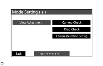
Select "View Adjustment" on the "Mode Setting (*)" screen to display the adjustment screen.
- HINT:
-
To select a grayed out item, select and hold the item for 2 seconds or more.
After checking the screen, press the "Next" button on the "Signal Check (*)" screen.
- NOTICE:
- ·
If performing the adjustment after proceeding to the next screen, confirm that all items display "OK" (blue) before selecting "Next".
·When "CHK" (red) is displayed, perform the inspections.
·The screen is displayed only when the shift signal is received via a direct line.
·It takes approximately 1 second to perform an OK judgement of CAN.
Display the adjustment screen. Then press the "Back" button to return to the Signal Check(*) screen.
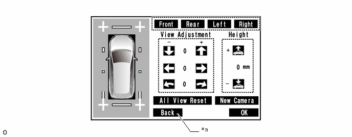
| *a | Back Button | - | - |
Select "Back" from the Signal Check(*) screen to display the Mode Setting(*) screen.
Cancel diagnosis mode and display the multi-media screen.
ECU data write
- HINT:
-
Input the items necessary for camera adjustment to the replacement parking assist ECU.
Using GTS, select "Chassis" → "Circumference Monitoring Camera Control Module" → "Utility" to perform utility.
- Chassis > Circumference Monitoring Camera Control Module > Utility
-
Tester Display ECU Data Write - 50005 470 4657
In accordance with the screen, perform ECU data write.
Enter diagnostic mode.
- CAUTION:
-
The check must be performed with the ignition switch to ON. Therefore, apply the parking brake, depress the brake pedal and move the shift position to P to ensure that the vehicle does not begin moving unexpectedly.
Select "Function Check/Setting" from the "Service Menu" screen.
Select "Camera Setting" on the "Function Check/Setting I" screen.
- NOTICE:
-
If the "Camera Setting" selection screen is not displayed, turn the ignition switch off and enter the diagnosis screen after turning the ignition switch to ON once again.
Select "View Adjustment" on the "Mode Setting (*)" screen to display the adjustment screen.
- HINT:
-
To select a grayed out item, select and hold the item for 2 seconds or more.
After checking the screen, press the "Next" button on the "Signal Check (*)" screen.
- NOTICE:
- ·
If performing the adjustment after proceeding to the next screen, confirm that all items display "OK" (blue) before selecting "Next".
·When "CHK" (red) is displayed, perform the inspections.
·The screen is displayed only when the shift signal is received via a direct line.
·It takes approximately 1 second to perform an OK judgement of CAN.
If data writing ends normally, "The view data writing was completed." is displayed.
Press "OK".