PARK ASSIST / MONITORING ULTRASONIC SENSOR(for Front) INSTALLATION
CAUTION / NOTICE / HINT
- HINT:
- ·
Use the same procedure for the RH and LH sides.
·The following procedure is for the LH side.
PROCEDURE

 89C48D
1.INSTALL FRONT CORNER ULTRASONIC SENSOR RETAINER (for Type A, for Off Road Package)
89C48D
1.INSTALL FRONT CORNER ULTRASONIC SENSOR RETAINER (for Type A, for Off Road Package)
- NOTICE:
- ·
Installing the front corner ultrasonic sensor retainer with some double-sided tape remaining may cause poor adhesion. Perform this procedure until the tape is sufficiently removed.
·Make sure to use a cloth when removing. Using a screwdriver, etc., may cause damage and poor adhesion.
- HINT:
-
Perform the following procedure only when replacement of a front corner ultrasonic sensor retainer is necessary.
Clean the front bumper assembly surface.
Remove any remaining double-sided tape from the front bumper assembly.
Wipe off any tape adhesive residue with cleaner.
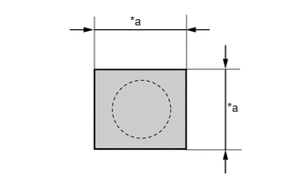
| *a | 30 mm (1.18 in.) |
Cover the sensor installation hole from the outside of the front bumper cover with a 30 mm (1.18 in.) square piece of tape.
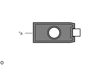
| *a | Scribed Line |

|
Primer Application |
Apply primer to the front bumper assembly on the installation area of the front corner ultrasonic sensor retainer using a brush or felt.
- NOTICE:
- ·
Replace the brush or felt if it is dirty or has become hardened.
·Keep any painted surface free from primer.
·If the primer contacts a painted surface, it may leave light primer marks. Therefore, use protective tape when using liquid primer.
·Do not touch surfaces to which primer has been applied until the front corner ultrasonic sensor retainer has been attached.
Let the primer dry sufficiently.
- NOTICE:
-
Do not touch applied surfaces until the primer is dry.
- Recommended drying time:
10 minutes or more (at 23°C (73°F))
Confirm that the primer has completely dried by touching the front bumper assembly. Then remove the tape.
Remove the peeling paper of the new front corner ultrasonic sensor retainer trying not to touch the adhesional surface.
- NOTICE:
-
After removing the peeling paper, do not touch the surface of the tape with your fingers or cotton work gloves.
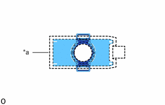
| *a | Scribed Line |
Align the front corner ultrasonic sensor retainer with the scribed line on the front bumper assembly and install it as shown in the illustration.
- NOTICE:
-
The application strength of the front corner ultrasonic sensor retainer will weaken if reapplied. If reapplication is necessary, be sure to replace it with a new one.
- HINT:
- ·
Apply pressure so that it does not lift up from the front bumper assembly.
·Pushing force: 30 N (3.1 kgf) for 3 seconds
89341L
2.INSTALL FRONT CENTER ULTRASONIC SENSOR
Connect the connector.
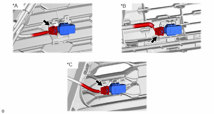
| *A | for Type A | *B | for Type B |
| *C | for Off Road Package | - | - |
Attach the claw to install the front center ultrasonic sensor as shown in the illustration.
- NOTICE:
- ·
When reusing the sensor, make sure that each sensor is returned to its original position.
·Check that the claw is securely fitted.
·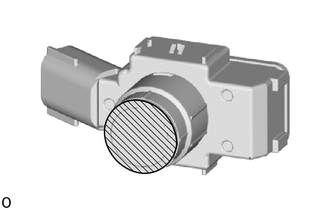 0,0 0,0 false
Microphone Surface
Do not push the microphone surface.
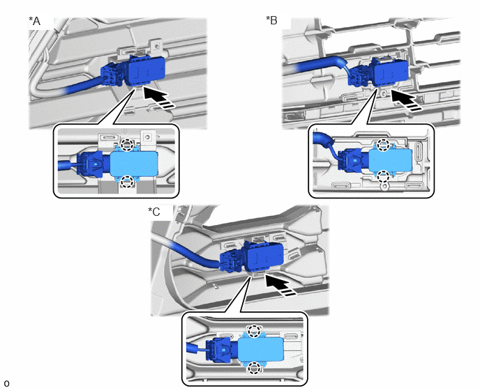
| *A | for Type A | *B | for Type B |
| *C | for Off Road Package | - | - |

|
Install in this Direction | - | - |
89341K
3.INSTALL FRONT CORNER ULTRASONIC SENSOR
Connect the connector.
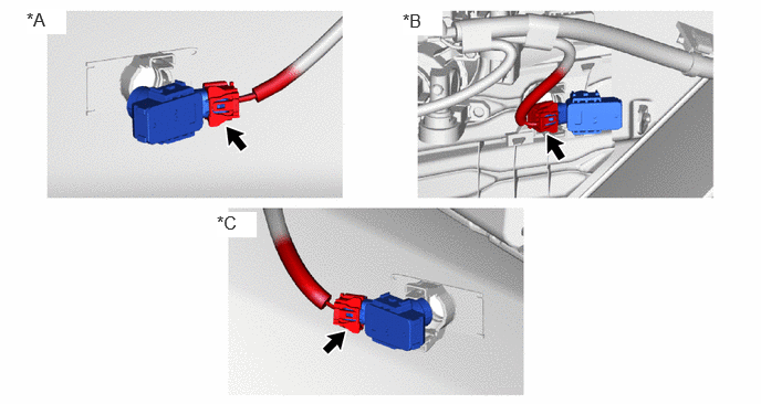
| *A | for Type A | *B | for Type B |
| *C | for Off Road Package | - | - |
for Type A:
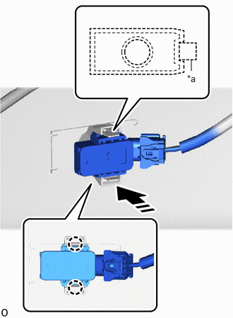
| *a | Protrusion of the mark |
|
|
Install in this Direction |
Attach the claw to install the front corner ultrasonic sensor as shown in the illustration.
- NOTICE:
- ·
When reusing the sensor, make sure that each sensor is returned to its original position.
·Check that the claw is securely fitted.
·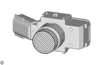 0,0 0,0 false
Microphone Surface
Do not push the microphone surface.
- HINT:
-
Align the connector with the protrusion of the mark when connecting it.
for Type B:
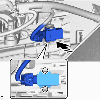
|
|
Install in this Direction |
Attach the claw to install the front corner ultrasonic sensor as shown in the illustration.
- NOTICE:
- ·
When reusing the sensor, make sure that each sensor is returned to its original position.
·Check that the claw is securely fitted.
·
0,0 0,0 false
Microphone Surface
Do not push the microphone surface.
for Off Road Package:
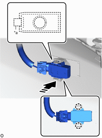
| *a | Protrusion of the mark |
|
|
Install in this Direction |
Attach the claw to install the front corner ultrasonic sensor as shown in the illustration.
- NOTICE:
- ·
When reusing the sensor, make sure that each sensor is returned to its original position.
·Check that the claw is securely fitted.
·
0,0 0,0 false
Microphone Surface
Do not push the microphone surface.
- HINT:
-
Align the connector with the protrusion of the mark when connecting it.
4.INSTALL FRONT BUMPER ASSEMBLY
86790B
5.ADJUST FRONT TELEVISION CAMERA ASSEMBLY (w/ Panoramic View Monitor System)