EXTERIOR PANELS / TRIM FRONT BUMPER(for Type A) INSTALLATION
CAUTION / NOTICE / HINT
- HINT:
- ·
When the front bumper is damaged or deformed due to an accident or contact with other objects, etc., or the bumper installation area on the body is repaired, it is necessary to perform millimeter wave radar sensor adjustment.
--Target Adjustment (Triangle Target):
-Target Adjustment (Flat Surface Target):
·A bolt without a torque specification is shown in the standard bolt chart.
PROCEDURE

 1.INSTALL FRONT BUMPER ASSEMBLY
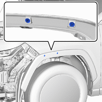
Install 2 new clips to the front fender moulding sub-assembly LH.
- NOTICE:
-
If the front bumper assembly has been removed, replace the clip with a new one.
- HINT:
-
Use the same procedure on the other side.
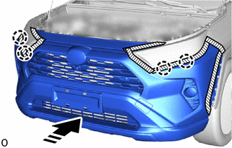

|
Install in this Direction |
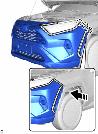
Attach the claw to temporarily install the front bumper assembly.
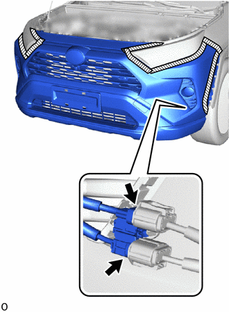
Connect the 2 connectors.
Install the front bumper assembly to the front bumper side retainer LH.
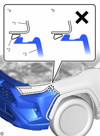
| *1 | Front Fender Panel |
| *2 | Front Bumper Side Retainer LH |
| *3 | Front Bumper Assembly |
| *a | Correct |
| *b | Incorrect |
Make sure that the front bumper assembly claw contacts the front bumper side retainer LH as shown in the illustration.
|
|
Install in this Direction |
Attach the claw to install the front bumper assembly as shown in the illustration.
- HINT:
-
Use the same procedure on the other side.
After installation, if there is a clearance and the front bumper assembly claw can be seen as shown in the illustration, the installation condition is incorrect. Perform the procedure from step 1 again.
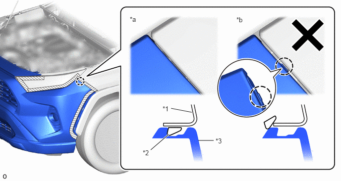
| *1 | Front Fender Panel | *2 | Front Bumper Side Retainer LH |
| *3 | Front Bumper Assembly | - | - |
| *a | Correct | *b | Incorrect |
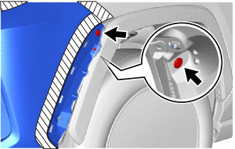
Install the 2 clips.
- HINT:
-
Use the same procedure on the other side.
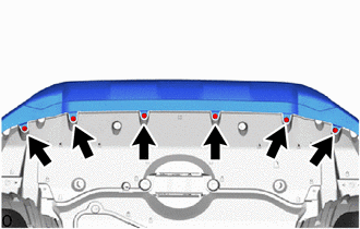
Install the 6 screws.
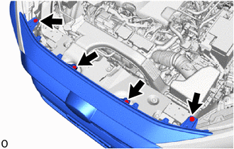
Install the 4 bolts.
Remove the protective tape.
75602A
2.INSTALL FRONT FENDER MOULDING SUB-ASSEMBLY LH
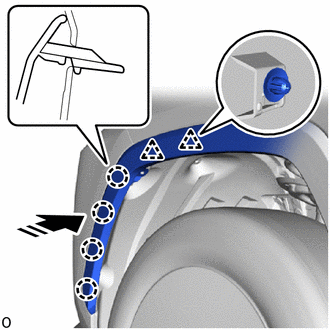
|
|
Install in this Direction |
Attach the clip and claw to install the front fender moulding sub-assembly LH.
Remove the protective tape.
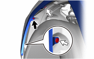

|
Screw |

|
Clip |
Install the 2 clips.
Install the screw.
75601A
3.INSTALL FRONT FENDER MOULDING SUB-ASSEMBLY RH
- HINT:
-
Use the same procedure described for the LH side.
53896B
4.INSTALL FRONT FENDER FRONT SPLASH SHIELD LH
53895B
5.INSTALL FRONT FENDER FRONT SPLASH SHIELD RH
- HINT:
-
Use the same procedure described for the LH side.
6.ADJUST FOG LIGHT ASSEMBLY
86790B
7.ADJUST FRONT TELEVISION CAMERA ASSEMBLY (w/ Panoramic View Monitor System)