STOP AND START STOP AND START SYSTEM After Engine Stops due to Stop and Start System, Engine does not Restart
DESCRIPTION
This is the troubleshooting procedure for situations where the engine does not restart after having been stopped by the stop and start system.
For information on stop and start control, refer to the system description.
CAUTION / NOTICE / HINT
PRECAUTIONS WHEN THE ENGINE STOP AND START ECU AND THE STARTER ASSEMBLY ARE REPLACED
- NOTICE:
- ·
When the engine stop and start ECU is replaced, it is necessary to read the number of starter operations before replacement and store this number in the new engine stop and start ECU after replacement, and to perform external backup boost converter (eco run vehicle converter assembly) existence learning. Moreover, initialization/learning of the air conditioning information and initialization/learning of the deceleration sensor zero point are also required.
·When the starter assembly is replaced, the number of starter operations stored in the engine stop and start ECU must be reset.
·When the starter assembly is replaced, "ST NO. 1 relay" must be also replaced.
·Inspect the fuses for circuits related to this system before performing the following procedure.
PRECAUTIONS WHEN BATTERY IS DISCHARGED AFTER LEAVING VEHICLE FOR A LONG TIME
- HINT:
-
If the vehicle has not been used for a long time, the battery charge may be low and stop and start control operation may be prohibited. After recharging the battery until the charging current decreases to 5 A or below, if the integrated current value still does not increase to the threshold value*1 or above, initialize the integrated current value*2 and drive the vehicle approximately 5 to 40 minutes until stop and start control operates.
*1: For information about the integrated current threshold value, refer to the system description.
*2: Use the GTS to perform Integrated Current Value Initialization.
PRECAUTIONS WHEN CONNECTING/DISCONNECTING CABLE TO/FROM NEGATIVE BATTERY TERMINAL
- HINT:
- ·
If the cable is disconnected from the battery terminal, stop and start control is prohibited until refresh charge is completed. In this case, let the vehicle idle to complete the refresh charge. The refresh charge is complete when the Data List item Status of Battery Charge Control changes from "Refresh Charge Mode". (Usually, idling the engine for 5 to 60 minutes with the battery fluid temperature at 11°C (52°F) or higher, the refresh charge will be completed.)
·If the GTS is not available and the Data List item Status of Battery Charge Control cannot be checked, charge the battery by idling the engine for approximately 5 to 60 minutes or driving the vehicle, and then drive the vehicle and check that stop and start control operates. If the engine is started with the hood open, the system determines that a jump start has occurred. Therefore, make sure that the hood is closed before starting the engine and driving the vehicle.
·After the refresh charge completes, turn the ignition switch off, wait for at least 30 seconds, and then start the engine again. If the vehicle enters refresh charge mode again while the engine is idling, the initial refresh charge did not properly complete, so wait for the refresh charge to complete.
(a)If power is not supplied to the navigation system or audio and visual system when the ignition switch is turned to ON for the first time after the battery has been reconnected, DTC P323A19 will be stored. Perform either of the following operations:
(1)Turn the ignition switch from ON to off twice.
(2)After turning the ignition switch from ON to off, clear the DTCs.
IF THE ENGINE FAILS TO RESTART FROM IDLING STOP
- NOTICE:
- If the engine fails to restart when stopped by stop and start control, the brake actuator may be activated. Brake actuator activation conditions:·
When the engine fails to restart when stopped by stop and start control.
·When the brake booster vacuum is insufficient.
·When the vehicle speed is 3 km/h (2 mph) or more and the brake pedal is depressed*.
*: When the engine is not running.
- HINT:
- ·
When the engine fails to restart when stopped by stop and start control and the brake booster vacuum is insufficient, the brake actuator is activated to ensure the braking force. When the brake actuator is activated, sound and vibration may be generated. This is not due to malfunction of the stop and start system or the vehicle.
PRECAUTIONS FOR FOUR-WHEEL TOWING
Do not tow the vehicle with all 4 wheels on the ground.
- NOTICE:
- ·
Towing the vehicle with all 4 wheels on the ground may have a detrimental effect on the stop and start system, and could lead to damage.
- HINT:
-
If it is absolutely necessary to tow the vehicle with all 4 wheels on the ground, before towing first turn the ignition switch off. Then, turn the ignition switch to ON without starting the engine, and tow the vehicle.
PRECAUTIONS WHEN REPLACING ECM
- NOTICE:
-
When the ECM is replaced on a vehicle with a non-specified battery, it is necessary to perform battery type switching.
PROCEDURE
Enter the following menus: Powertrain / Stop and Start / Utility / Vehicle Control History (RoB).
- Powertrain > Stop and Start > Utility
-
Tester Display Vehicle Control History (RoB) - 50005 392 55
Check vehicle control history.
- Result:
Result Proceed to Vehicle control history item Hood Open during Stop&Start (Engine Stall) stored A Vehicle control history item Hood Open during Stop&Start (Engine Stall) not stored B
A
B
Check the condition of the engine hood.
Check with the driver to confirm whether or not the engine hood was opened during stop and start control.
- Result:
Result Proceed to Engine hood was not opened during stop and start control A Engine hood was opened during stop and start control B
A
B
Consult with the customer to determine if they performed operations that could result in an AT engine stall.
- HINT:
-
(ex.) Heavy load, frequent shifts, etc.
- Result:
Result Proceed to Driver operations that could cause engine stall were performed A None of the above conditions are met B
A
B
Following the instructions on the GTS screen, check for engine control system DTCs.
- Result:
Result Proceed to Engine control system poor startability DTCs or RoBs not output, but engine control system poor startability related DTCs or RoBs are output.
- HINT:
- ·
"Engine stall" DTCs, misfires, poor fuel pressure, crank angle sensor, etc.
·If engine control system poor startability DTCs/RoBs are output, first check that there was not a failure to restart from Stop and Start in "8. CHECK VEHICLE CONTROL HISTORY AND PROBLEM SYMPTOMS", and then check "Engine control system poor startability DTCs /RoBs".
A None of the above conditions are met ·After engine stalls, when starting engine using key or push switch operation, starter does not rotate.
·Even after vehicle brought in, when starting engine using key or push switch operation, starter does not rotate.
B ·When restarting engine from idling stop, starter did not rotate.
·Even after vehicle brought in, when restarting engine from idling stop, starter does not rotate.
C ·When restarting engine from idling stop, starter rotated.
·Unknown whether starter rotated (does not remember).
D
A
Diagnostic trouble code chart :
for M20C-FKS:
for M20D-FKS:
Vehicle control history (RoB):
for M20C-FKS:
for M20D-FKS:
B
C
Inspect battery
for M20C-FKS:
for M20D-FKS:
D
Perform an operation check of the stop and start system to confirm what kind of operations result in the engine failing to restart after it has been stopped by the stop and start system.
- Result:
Result Proceed to While vehicle is stopped with the engine stopped by idling stop, the engine cannot restart when attempting to drive forward. A During idling stop, an operation that should restart the engine (brake off, shift operation, etc.) is performed, but there is no response to the start request (refer to Data List). B
A
B
Check the Data List items for countermeasures, and inspect the possible causes of engine start requests not being issued.
- HINT:
-
Depending on vehicle, some items may not be displayed.
| Countermeasures and Related Areas | Start Conditions |
|---|---|
When the engine is stopped by stop and start control, and the brakes are operated but a start request is not issued, inspect the following components:
·
Stop light switch (ECM) ·
Stop light switch (ABS/VSC) ·
Brake master pressure sensor (Brake system) ·
Acceleration sensor ·
Stop light switch circuit |
·
Data List / Stop Light SW (ECM) (OFF: Release brake pedal) ·
Data List / Stop Light SW (ABS/VSC) (OFF: Release brake pedal) ·
Data List / Master Cylinder Pressure (Release brake pedal (However, when brake hold is operating, even though the brake pedal is released there is no intention of forward motion, so the engine will not start)) |
| Countermeasures and Related Areas | Start Conditions |
|---|---|
When the engine is stopped by stop and start control, and the driver exits the vehicle but a start request is not issued, inspect the following components:
·
Driver seat seat belt buckle switch circuit (DTC U014087 (Main body system communication interrupted)) ·
Front seat inner belt assembly RH ·
Driver seat courtesy switch circuit (DTC U014087 (Main body system communication interrupted)) ·
Driver seat courtesy switch circuit |
·
Data List / Driver Courtesy Switch Signal (ON: Driver door open) ·
Driver seat seat belt unfastened |
| Countermeasures and Related Areas | Start Conditions |
|---|---|
When the engine is stopped by stop and start control, and a shift operation is performed but a start request is not issued, inspect the following components:
·
Shift lever assembly ·
Engine control ECU (or transmission control ECU) |
Data List / Shift Position (Other than D or P) |
| Countermeasures and Related Areas | Start Conditions |
|---|---|
When the engine is stopped by stop and start control, and the stop and start cancel switch is pressed but a start request is not issued, inspect the following components:
·
Stop and start cancel switch circuit |
Data List / Stop&Start Cancel Switch (ON: Stop and start system cancel switch (eco run cancel switch assembly) pressed |
| Countermeasures and Related Areas | Start Conditions |
|---|---|
When the engine is stopped by stop and start control, and a steering operation is performed but a start request is not issued, inspect the following components:
·
Steering sensor ·
Steering system ·
Engine stop and start ECU |
Data List / Steering Angle (Steering angle 10 deg or more since idling stop) |
| Countermeasures and Related Areas | Start Conditions |
|---|---|
When the engine is stopped by stop and start control, and a clutch operation is performed but a start request is not issued, inspect the following components:
·
Clutch upper switch ·
Engine stop and start ECU |
OFF: Clutch pedal depressed |
| Countermeasures and Related Areas | Start Conditions |
|---|---|
When the engine is stopped by stop and start control, and a clutch operation is performed but a start request is not issued, inspect the following components:
·
Clutch lower switch ·
Engine stop and start ECU |
ON: Clutch pedal is fully depressed all the way |
| Countermeasures and Related Areas | Start Conditions |
|---|---|
·
Check the heater and air conditioner system conditions. ·
When the heater and air conditioner system start conditions are fulfilled but a start request is not issued, inspect the following components: Heater and air conditioner system |
·
Air conditioning amplifier assembly internal counter ended ·
All of the following conditions apply: -
Blower Switch: ON condition -
Evaporator temperature is at or above the threshold value (threshold varies according to factors including temperature, humidity and sunlight amount levels) ·
Any of the following conditions apply: -
Blower Switch, A/C Switch: Changed from OFF to ON -
Defogger switch (front defroster): Turned from OFF to ON -
Changed from stop and start priority control to normal control |
| Countermeasures and Related Areas | Start Conditions |
|---|---|
When the engine is stopped by stop and start control, and the accelerator pedal is depressed but a start request is not issued, inspect the following components:
·
Accelerator Pedal Sensor ·
Engine control ECU (or transmission control ECU) |
Data List / Idle (OFF: Accelerator pedal is depressed) |
| Countermeasures and Related Areas | Start Conditions |
|---|---|
When the engine is stopped by stop and start control, and the brake pedal is depressed further or the brakes are pumped repeatedly but a start request is not issued, inspect the following components:
·
Brake booster vacuum decreased ·
Vacuum sensor assembly or vacuum sensor assembly (atmospheric pressure sensor) ·
Brake booster assembly ·
Brake master pressure sensor (Brake system) ·
Engine stop and start ECU |
Data List / Brake Negative Pressure (Decreased vacuum inside brake booster (less than 37.5 kPa)(varies with brake master fluid pressure)) |
| Countermeasures and Related Areas | Start Conditions |
|---|---|
When the engine is stopped by stop and start control, and push start switch / key operation is performed but a start request is not issued, inspect the following components:
·
Smart key ECU assembly (Push start switch)/IG Switch (Mechanical key) ·
Push start switch ·
Engine stop and start ECU |
·
Starter is operating ·
When Data List / Starter Type (Tandem Starter): -
Data List / Starter Motor (ON: During cranking) ·
When Starter Type (Other than Tandem Starter): Data List / Starter (ON: During starter operation) |
| Countermeasures and Related Areas | Start Conditions |
|---|---|
When the engine is stopped by stop and start control with the transmission in the P position, and the brake pedal is depressed but a start request is not issued, inspect the following components:
·
Shift lever assembly ·
Stop light switch circuit ·
Engine control ECU (or transmission control ECU) ·
Engine stop and start ECU ·
Skid control ECU (brake actuator assembly) |
·
Data List / Stop And Start Control Mode (Stop condition: Engine stopped by stop and start control) ·
Data List / Shift Position (P) ·
Data List / Stop Light SW (ABS/VSC) (ON: Depress brake pedal -> OFF: Release brake pedal -> ON: Depress brake pedal) ·
Data List / Stop Light SW (EFI) (ON: Depress brake pedal -> OFF: Release brake pedal -> ON: Depress brake pedal) ·
Data List / Brake Fluid Pressure (0.04 MPa or more) |
| Countermeasures and Related Areas | Start Conditions |
|---|---|
If the preceding vehicle starts moving but the Data List is OFF, inspect the following:
·
Dynamic radar cruise control system ·
Engine stop and start ECU |
·
When the vehicle is stopped with the all-speed dynamic radar cruise control system operating, the preceding vehicle starts to move or the user performs a resume operation (starts to move the vehicle) ·
When condition prohibited according to dynamic radar cruise control system |
| Countermeasures and Related Areas | Start Conditions |
|---|---|
If the air suspension system is operating but the Data List is OFF, inspect the following:
·
Air suspension system |
When condition not prohibited according to adaptive variable suspension system |
| Countermeasures and Related Areas | Start Conditions |
|---|---|
If the intelligent parking system is operating but the Data List is OFF, inspect the following:
·
Intelligent parking assist system ·
Engine stop and start ECU |
When condition prohibited according to intelligent parking assist system |
| Countermeasures and Related Areas | Start Conditions |
|---|---|
If the welcab system is operating but the Data List is OFF, inspect the following:
·
Welcab system |
When condition not prohibited according to Welcab system |
| Countermeasures and Related Areas | Start Conditions |
|---|---|
If the driving mode is being operated the Data List is OFF, inspect the following:
·
Rear differential lock ·
Drive mode ·
Snow Mode |
·
Data List / Rear Differential Lock Operating Status (ON: Lock) ·
Except NORMAL, ECO or COMFORT modes ·
Snow mode ON |
Enter the following menus: Powertrain / Stop and Start / Utility / Vehicle Control History (RoB).
- Powertrain > Stop and Start > Utility
-
Tester Display Vehicle Control History (RoB) - 50005 392 55
Select a vehicle control history item to display the data from the time of control.
Check the output data.
- HINT:
- ·
Checking the freeze frame data allows the vehicle conditions at the time of detection to be confirmed.
·As Vehicle Control History may be overwritten whenever the trigger conditions are met, make sure to save the Vehicle Control History data before performing any inspections.
- Result:
Result Proceed to NO is displayed for Engine Start Fail in the vehicle control history A Yes is displayed for Engine Start Fail in the vehicle control history B
A
Diagnostic trouble code chart :
for M20C-FKS:
for M20D-FKS:
Vehicle control history (RoB):
for M20C-FKS:
for M20D-FKS:
B
Enter the following menus: Powertrain / Stop and Start / Utility / Vehicle Control History (RoB).
- Powertrain > Stop and Start > Utility
-
Tester Display Vehicle Control History (RoB) - 50005 392 55
Select a vehicle control history item to display the data from the time of control.
Check the output data.
- HINT:
- ·
Checking the freeze frame data allows the vehicle conditions at the time of detection to be confirmed.
·As Vehicle Control History may be overwritten whenever the trigger conditions are met, make sure to save the Vehicle Control History data before performing any inspections.
- Result:
Result Proceed to All recorded sections Starter Motor = OFF, and all recorded sections Engine Speed = 0 rpm
- HINT:
-
It is possible that the starter drive command is not being sent from the engine stop and start ECU.
A Starter Motor = ON for any sections, and all recorded sections Engine Speed = 0 rpm
- HINT:
-
It is possible that the drive command is being sent from the engine stop and start ECU but the starter itself is not moving.
B Engine Speed > 0 rpm for any sections
- HINT:
-
It is possible that cranking was achieved but the engine stopped.
C
A
- HINT:
-
It is possible that there is a malfunction of the starter drive circuit inside the stop and start ECU.
B
C
Enter the following menus: Powertrain / Stop and Start / Utility / Vehicle Control History (RoB).
- Powertrain > Stop and Start > Utility
-
Tester Display Vehicle Control History (RoB) - 50005 392 55
Select a vehicle control history item to display the data from the time of control.
Check the output data.
- HINT:
- ·
Checking the freeze frame data allows the vehicle conditions at the time of detection to be confirmed.
·As Vehicle Control History may be overwritten whenever the trigger conditions are met, make sure to save the Vehicle Control History data before performing any inspections.
- Result:
Result Proceed to Cranking Time is 1.5 seconds or more
- HINT:
-
It is possible that there is an external malfunction outside of the stop and start ECU (drive circuit).
A Cranking Time is less than 1.5 seconds
- HINT:
-
It is possible that there is a malfunction in the stop and start ECU (drive circuit).
B
A
B
Disconnect the engine stop and start ECU connector.
Turn the ignition switch to ON.
Turn off any electrical loads.
Measure the voltage according to the value(s) in the table below.
- OK:
11 V or higher
- Standard Voltage:
Tester Connection Switch Condition Specified Condition A34-1 (+B) - Body ground Ignition switch ON 11 V or higher
- Result:
Proceed to OK NG
OK
NG
Enter the following menus: Powertrain / Stop and Start / Utility / Vehicle Control History (RoB).
- Powertrain > Stop and Start > Utility
-
Tester Display Vehicle Control History (RoB) - 50005 392 55
Select a vehicle control history item to display the data from the time of control.
Check the output data.
- HINT:
- ·
Checking the freeze frame data allows the vehicle conditions at the time of detection to be confirmed.
·As Vehicle Control History may be overwritten whenever the trigger conditions are met, make sure to save the Vehicle Control History data before performing any inspections.
·Depending on RoB detection timing, the minimum voltage from the previous startup will be stored for the Minimum Voltage (Cranking) and the Minimum Voltage (Starter Solenoid Engagement). For the battery condition at the start of the current driving cycle, see Battery Voltage.
·When the value is 20 V, the value is being calculated.
- Result:
Result Proceed to Battery voltage is 8.92 V or more A Battery voltage is less than 8.92 V B
A
B
Measure the voltage of the battery.
- Standard voltage:
11 to 14 V
- Result:
Proceed to OK NG
OK
NG
Enter the following menus: Powertrain / Stop and Start / Utility / Vehicle Control History (RoB).
- Powertrain > Stop and Start > Utility
-
Tester Display Vehicle Control History (RoB) - 50005 392 55
Select a vehicle control history to display the Cranking Time and Starter OFF Permission History (ECM) data from the time of control.
Check the output data.
- HINT:
- ·
Checking the freeze frame data allows the vehicle conditions at the time of detection to be confirmed.
·As Vehicle Control History may be overwritten whenever the trigger conditions are met, make sure to save the Vehicle Control History data before performing any inspections.
- Result:
Result Proceed to Cranking Time is less than 1.5 seconds Starter OFF Permission History (ECM) is ON
- HINT:
-
It is possible that the ECM made a judgment of complete combustion and the ECM then stopped the starter.
A Starter OFF Permission History (ECM) is OFF
- HINT:
-
It is possible that the engine stop and start ECU made a judgment of complete combustion and the engine stop and start ECU then stopped the starter.
B Cranking Time is 1.5 seconds or more
- HINT:
-
It is possible that the stop and start ECU did not stop the starter.
- C
A
for M20C-FKS:
for M20D-FKS:
- HINT:
-
Check whether the speed value of the EFI ECU is not a higher value than the original NE.
B
C
Enter the following menus: Powertrain / Stop and Start / Data List / Engine Speed and Engine Speed (ECM).
- Powertrain > Stop and Start > Data List
-
Tester Display Engine Speed Engine Speed (ECM) - 50003 392 502,213
Compare the Data List items displayed on the GTS.
- Result:
Result Proceed to Engine Speed > Engine Speed (ECM) + 100 rpm A None of the above conditions are met B
A
B
Enter the following menus: Powertrain / Stop and Start / Utility / Vehicle Control History (RoB).
- Powertrain > Stop and Start > Utility
-
Tester Display Vehicle Control History (RoB) - 50005 392 55
Select a vehicle control history item to display the data from the time of control.
Check the data points in the data that was output.
- HINT:
- ·
Checking the freeze frame data allows the vehicle conditions at the time of detection to be confirmed.
·As Vehicle Control History may be overwritten whenever the trigger conditions are met, make sure to save the Vehicle Control History data before performing any inspections.
- Result:
Result Proceed to For each and all of the data points, Engine Speed > Engine Speed (ECM) + 100 rpm A None of the above conditions are met B
A
B
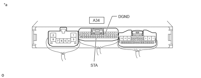
| *a | Component with harness connected
(Engine Stop and Start ECU) |
- | - |
Enter the following menus: Powertrain / Stop and Start / Active Test / Starter (Hood Close)
- Powertrain > Stop and Start > Active Test
-
Tester Display Starter(Hood Close) - 50004 392 42017
Measure the voltage according to the value(s) in the table below.
- Standard Voltage:
Tester Connection Condition Specified Condition A34-21 (STA) - A34-6 (DGND) Performing Active Test, while cranking. 6 to 14 V
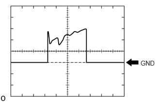
Using an oscilloscope, measure the waveform immediately after starting.
| Item | Content |
|---|---|
| Tester Connection | A34-21 (STA) - A34-6 (DGND) |
| Tool Setting | 10 V/DIV, 200 ms./DIV |
| Condition | During cranking |
- OK:
Voltage and waveform both normal
- Result:
Proceed to OK NG
OK
for M20C-FKS:
for M20D-FKS:
NG
| *a | Component with harness connected
(Engine Stop and Start ECU) |
- | - |
Enter the following menus: Powertrain / Stop and Start / Active Test / Starter (Hood Close)
- Powertrain > Stop and Start > Active Test
-
Tester Display Starter(Hood Close) - 50004 392 42017
Measure the voltage according to the value(s) in the table below.
- Standard Voltage:
Tester Connection Condition Specified Condition A34-21 (STA) - A34-6 (DGND) Performing Active Test, while cranking. 6 to 14 V
Using an oscilloscope, measure the waveform immediately after starting.
| Item | Content |
|---|---|
| Tester Connection | A34-21 (STA) - A34-6 (DGND) |
| Tool Setting | 10 V/DIV, 200 ms./DIV |
| Condition | During cranking |
- OK:
Voltage and waveform both normal
- Result:
Proceed to OK NG
OK
for M20C-FKS:
for M20D-FKS:
NG
Enter the following menus: Powertrain / Stop and Start / Utility / Vehicle Control History (RoB).
Select a vehicle control history item to display the data from the time of control.
Check the output data.
- HINT:
- ·
Checking the freeze frame data allows the vehicle conditions at the time of detection to be confirmed.
·As Vehicle Control History may be overwritten whenever the trigger conditions are met, make sure to save the Vehicle Control History data before performing any inspections.
- Result:
Result Proceed to When Starter Motor is ON, there is even 1 point at which Engine Speed < 300 rpm A None of the above conditions are met B
A
B
Check how long it took the engine to stall after turning the starter off.
- Result:
Result Proceed to After starter turned off, engine immediately stalls.
- HINT:
-
Engine stalls within 2 seconds.
A After starter turned off, engine stalls after a time. B
A
for M20C-FKS:
for M20D-FKS:
B
for M20C-FKS:
for M20D-FKS: