M20C-FKS ENGINE CONTROL SFI SYSTEM Engine Difficult to Start
DESCRIPTION
| Problem Symptom | Suspected Area | Trouble Area | |
|---|---|---|---|
·
Engine does not crank ·
Engine cranks slowly |
·
Battery depletion ·
Starter malfunction |
Starter system | ·
Battery depletion ·
Starter malfunction ·
Starter circuit |
| Excessive engine friction | Engine | Engine assembly | |
·
Starting time is long ·
Engine speed fluctuation due to abnormal combustion ·
Idle speed too low or high ·
The engine stalls immediately after starting Strong engine vibration due to above symptoms |
·
Ignition malfunction ·
Deviation in air fuel ratio (Excessive or insufficient intake air volume or fuel supply) ·
Insufficient compression ·
Changes in load from another system |
Ignition system | ·
Spark plug ·
Ignition coil assembly |
| Fuel system | ·
Direct fuel injector assembly ·
Port fuel injector assembly ·
Fuel pump (for high pressure side) ·
Fuel pump (for low pressure side) ·
Fuel pump control circuit ·
Fuel suction plate sub-assembly ·
Fuel main valve assembly ·
Fuel line ·
Purge VSV system ·
Fuel quality (existence of foreign matter, degradation) |
||
| Intake and exhaust systems | ·
EGR system ·
Mass air flow meter sub-assembly ·
Intake system (Air leaks or deposit accumulation) ·
Throttle body with motor assembly ·
Air fuel ratio sensor (sensor 1) ·
Air fuel ratio sensor (sensor 2) ·
Cam timing control motor with EDU assembly ·
Cam timing oil control solenoid assembly ·
Variable Valve Timing system (VVT system) |
||
| Other control systems | ·
ECM ·
Wire harness or connector ·
Knock control sensor ·
Engine coolant temperature sensor ·
Immobiliser system |
||
| Engine | ·
Water inlet with thermostat sub-assembly ·
Engine assembly ·
Crankshaft position sensor malfunction |
||
| High load from another system | ·
Air conditioning system ·
Power steering system ·
Electrical load signal system ·
CVT system |
||
SYMPTOM AND CAUSE OF SYSTEM MALFUNCTION
- HINT:
-
The following are descriptions of the characteristics of each system malfunction. After understanding the link between the causes and symptoms, perform the inspection of each component. Even if the problem symptom does not recur, signs of the malfunction may be found in the Data List.
Ignition system
| Main cause of malfunction | Performance degradation (wear, existence of foreign matter, etc.) |
| Symptom | Engine speed fluctuation due to abnormal combustion |
| Data List | Misfire Count Cylinder #1 to #4 |
|
|
| Main cause of malfunction | Internal malfunction |
| Problem symptom | Engine speed fluctuation due to abnormal combustion |
| Data List | Misfire Count Cylinder #1 to #4 |
Fuel system
| Main cause of malfunction | Blockage, leak |
| Problem symptom | ·
Engine speed fluctuation due to abnormal combustion ·
Idle speed too low or high ·
Engine is difficult to start due to high concentration of HC |
| Data List | ·
Target Air-Fuel Ratio ·
Short FT B1S1 ·
Long FT B1S1 ·
Total FT Bank 1 ·
Fuel System Status Bank 1 ·
A/F Learn Value Idle (Port) Bank 1 ·
A/F Learn Value Low (Port) Bank 1 ·
A/F Learn Value Mid No.1 (Port) Bank 1 ·
A/F Learn Value Mid No.2 (Port) Bank 1 ·
A/F Learn Value High (Port) Bank 1 ·
A/F Learn Value Idle Bank 1 ·
A/F Learn Value Low Bank 1 ·
A/F Learn Value Mid No.1 Bank 1 ·
A/F Learn Value Mid No.2 Bank 1 ·
A/F Learn Value High Bank 1 |
|
|
| Main cause of malfunction | Fuel suction plate sub-assembly or fuel main valve assembly malfunction |
| Problem symptom | Engine is difficult to start due to insufficient fuel supply |
|
|
| Main cause of malfunction | ·
Fuel degradation due to age or water contamination ·
Low fuel quality ·
Addition of fuel additive |
| Problem symptom | ·
Engine speed fluctuation due to abnormal combustion ·
Idle speed too low or high ·
Engine is difficult to start |
Intake and exhaust systems
| Main cause of malfunction | Improper operation, sticking |
| Problem symptom | ·
Engine speed fluctuation due to abnormal combustion ·
Idle speed too low or high ·
Engine is difficult to start, lacks power or stalls |
| Data List | ·
Target EGR Valve Position No.1 ·
EGR Step Position -
Normal condition: Actual EGR valve position = Target EGR valve position +/-5% (Fully closed: 0%, Fully open: 100%) -
Perform the Active Test "Control the EGR Step Position" and check if the vehicle condition changes when the EGR valve position is changed -
When the ignition switch is turned to ON (engine not started), the EGR valve is fully closed |
| Main cause of malfunction | Performance degradation (existence of foreign matter, etc.) |
| Problem symptom | Lack of power |
| Data List | Mass Air Flow Sensor |
|
|
| Main cause of malfunction | Inappropriate trim volume adjustment due to accumulation of deposits |
| Problem symptom | ·
Engine speed fluctuation due to abnormal combustion ·
Idle speed too low or high ·
Lack of power |
| Data List | ·
Engine Stall Control F/B Flow ·
ISC F/B Learn Torque ·
ISC Total AUXS Torque ·
ISC F/B Torque ·
Sum of ISC F/B Torque (Recent) ·
ISC AUXS Torque (Alternator) ·
ISC AUXS Torque (Air Conditioner) ·
Throttle Air Flow F/B Value |
| Main cause of malfunction | Deviation in sensor characteristics |
| Problem symptom | Abnormal combustion due to deviation of actual air fuel ratio from calculated ratio |
| Data List | ·
A/F (O2) Sensor Current B1S1 ·
A/F (O2) Sensor Current B1S2 ·
Fuel System Status Bank 1 |
Engine
| Main cause of malfunction | ·
Compression loss ·
Accumulation of deposits (Combustion chamber, intake valve or intake manifold) |
| Problem symptom | ·
Engine speed fluctuation due to abnormal combustion ·
Idle speed too low or high ·
Hesitation during acceleration or stalling |
|
|
Data List Items Related to Engine Difficult to Start
- HINT:
-
Depending on the vehicle model, the applicable Data List items may vary. Data List items other than the ones used in the diagnostic procedure are for reference only.
- ·
Mass Air Flow Sensor
·Engine Stall Control F/B Flow
·ISC F/B Learn Torque
·ISC Total AUXS Torque
·ISC F/B Torque
·Sum of ISC F/B Torque (Recent)
·ISC AUXS Torque (Alternator)
·ISC AUXS Torque (Air Conditioner)
·Throttle Air Flow F/B Value
·Target Fuel Pressure (High)
·Target Fuel Pressure (Low) / Target Fuel Pressure 2
·Fuel Pressure (High)
·Fuel Pressure (Low) / Fuel Pressure 2
·High Pressure Fuel Pump Duty Ratio (D4)
·High Pressure Fuel Pump Discharge Rate
·Target Air-Fuel Ratio
·A/F (O2) Sensor Current B1S1
·A/F (O2) Sensor Current B1S2
·Short FT B1S1
·Long FT B1S1
·Total FT Bank 1
·Fuel System Status Bank 1
·A/F Learn Value Idle (Port) Bank 1
·A/F Learn Value Low (Port) Bank 1
·A/F Learn Value Mid No.1 (Port) Bank 1
·A/F Learn Value Mid No.2 (Port) Bank 1
·A/F Learn Value High (Port) Bank 1
·A/F Learn Value Idle Bank 1
·A/F Learn Value Low Bank 1
·A/F Learn Value Mid No.1 Bank 1
·A/F Learn Value Mid No.2 Bank 1
·A/F Learn Value High Bank 1
·Target EGR Valve Position No.1
·EGR Step Position
·Misfire Count Cylinder #1
·Misfire Count Cylinder #2
·Misfire Count Cylinder #3
·Misfire Count Cylinder #4
Vehicle Control History Freeze Frame Data Items Related to Engine Difficult to Start
- HINT:
-
The frequency of the malfunction can be determined by confirming the number of times the symptom occurred.
- ·
Engine Difficult to Start Count (Engine Starting Time Long)
·Engine Difficult to Start Count (Immobiliser)
CAUTION / NOTICE / HINT
- HINT:
- ·
If any other DTCs are output, perform troubleshooting for those DTCs first.
·Make sure to reproduce the conditions present when the malfunction occurred.
·Using the GTS, read the Data List to confirm the engine operating conditions. This information can be useful when troubleshooting.
·The vehicle condition when the problem symptoms occurred can be determined using the Vehicle Control History.
·As the Vehicle Control History data may be overwritten whenever the trigger conditions are met, make sure to save the Vehicle Control History data before performing any inspections.
·If the problem symptoms do not recur, attempt to reproduce the symptoms and conditions when the malfunction occurred based on the result of the customer problem analysis and Vehicle Control History. Place the priority on confirming the symptoms.
·When performing inspections, jiggle the relevant wire harnesses and connectors in an attempt to reproduce malfunctions that do not always occur.
·The suspected cause of the problem symptoms can be determined using the codes, items, and Freeze Frame Data within the Vehicle Control History.
·When confirming the Freeze Frame Data, be sure to check all multi Freeze Frame Data.
·When confirming the Freeze Frame Data, if there are multiple items related to the cause of the malfunction, perform troubleshooting for all related items.
·If the malfunction is currently occurring, use the Data List to confirm the current vehicle condition. By using the Data List, more detailed vehicle information can be confirmed than by using the Vehicle Control History Freeze Frame Data by itself.
·As Vehicle Control History may be stored when performing an Active Test, learning, etc., make sure to clear the Vehicle Control History before returning the vehicle to the customer.
·If the engine is started immediately after reconnecting the battery terminal, the engine may stall immediately after it starts due to the intercommunication process between each ECU. For this reason, when starting the engine after reconnecting the battery terminal, first turn the ignition switch to ON and then wait several seconds for the communication process to complete before starting the engine.
PROCEDURE
Interview the customer for details about the conditions when the engine was difficult to start.
- HINT:
-
In addition to the usual questions, be sure to ask the customer about the specific details when the problem symptoms occurred.
Condition When Problem Symptom Occurred Suspected Area After refueling at an unfamiliar gas station, the engine became difficult to start. Fuel quality After the addition of fuel additives, the engine became difficult to start. Addition of fuel additive Only after leaving the vehicle for a long time, the engine becomes difficult to start. Leaking fuel injector assembly The vehicle mostly driven for short distances only. Formation of carbon deposits on spark plug
- Result:
Proceed to NEXT
NEXT
Connect the GTS to the DLC3.
Turn the ignition switch to ON.
Turn the GTS on.
Perform a road test.
Enter the following menus: Powertrain / Engine / Trouble Codes.
Read the DTCs.
- Powertrain > Engine > Trouble Codes
- 50001 372
- Result:
Result Proceed to DTCs are not output A DTC is output B
A
B
Connect the GTS to the DLC3.
Turn the ignition switch to ON.
Turn the GTS on.
Enter the following menus: Powertrain / Engine / Utility / Vehicle Control History (RoB).
- Powertrain > Engine > Utility
-
Tester Display Vehicle Control History (RoB) - 50005 372 55
- HINT:
-
It is also possible to display vehicle control history during the Health Check, if "Store All Data" is selected.
Confirm if any data relating to the problem symptoms exist in the Vehicle Control History.
- HINT:
- ·
The vehicle condition when the problem symptoms occurred can be determined by confirming the Vehicle Control History Freeze Frame Data.
·As the Vehicle Control History data may be overwritten whenever the trigger conditions are met, make sure to save the Vehicle Control History data before performing any inspections.
·Using information from the customer about when the problem symptom occurred, find the Freeze Frame Data with the appropriate Key Cycle, Total Distance Traveled, etc., to find vehicle history that may be related to the problem symptoms.
Check if the problem symptoms stated by the customer are currently occurring.
- HINT:
- ·
By using snapshot to store the Data List, the Data List items can be compared to the Vehicle Control History.
·If the problem symptoms cannot be reproduced, refer to Check for Intermittent Problems, and try to reproduce the conditions when the problem symptoms occurred as stated by the customer. If the problem symptoms still cannot be reproduced, perform the following procedure.
Read the Data List or the Vehicle Control History Freeze Frame Data.
- HINT:
- ·
If the malfunction is currently occurring, compare the values of the Data List items with the vehicle control history freeze frame data.
·If the malfunction is not currently occurring, read the Vehicle Control History Freeze Frame Data.
- Result:
Vehicle Control History Vehicle Control History Freeze Frame Data / Data List While Problem Symptoms Are Occurring Suspected Area Proceed to Engine Difficult to Start (Engine Starting Time Long) is stored
(Vehicle Control History Code: X0810)Engine speed is 0 rpm (engine does not crank) Battery depletion, excessive engine friction, starter malfunction or crankshaft position sensor malfunction A Engine speed is between 100 and 500 rpm (engine cranks but combustion does not occur, initial combustion delays or combustion occurs late) Ignition system, fuel system malfunction or wire harness B Engine Difficult to Start (Engine Stall Immediately After Starting) is stored
(Vehicle Control History Code: X0811)- ·Improper fuel injection volume (too low or too high)
·If Long FT is out of specified range: insufficient fuel supply due to clogging of injectors or fuel pump
·If engine cranking speed is high: compression loss due to deposits caught on valves
B ISC F/B Learn Torque is 15 Nm or higher The offset correction value is insufficient due to deposits in the throttle body causing a low idle air flow rate. C Engine Difficult to Start (Immobiliser) is stored
(Vehicle Control History Code: X0812)- The engine stalled due to operation of immobiliser system. Check the immobiliser system for malfunctions. D The malfunction is not currently occurring and there is no Vehicle Control History related to the problem symptoms stated by the customer. B
A
B
C
D
Check the interview result.
- Result:
Result Proceed to Engine is difficult to start only when the vehicle has been left as is for a long time (1 hour or more) A Other than above B
A
B
Check for leaks from the port fuel injector assembly.
- HINT:
- ·
The port fuel injector assembly may have a sealing problem.
·Perform "Inspection After Repair" after replacing the port fuel injector assembly.
- Result:
Proceed to OK NG
OK
NG
Check the engine cranking operation.
- Result:
Result Proceed to The engine does not crank or cranks slowly A The engine cranks normally B
A
B
- Result:
Proceed to OK NG
OK
NG
Check if the problem symptoms reported in the customer problem analysis recur.
- HINT:
-
If the problem symptoms do not recur, attempt to reproduce the conditions when the malfunction occurred based on the result of the customer problem analysis.
- Result:
Result Proceed to The problem symptom recurs A The problem symptom does not recur (occurred in the past) B
A
B
Check that the engine starts or there is initial combustion.
- HINT:
-
If there is no initial combustion, perform a simple spark test by removing the bolt of the ignition coil assembly, partially lifting the ignition coil assembly, and checking for spark.
- Result:
Result Proceed to The engine starts or there is initial combustion A There is no initial combustion and no spark occurs B
A
B
Connect the GTS to the DLC3.
Turn the ignition switch to ON.
Turn the GTS on.
Enter the following menus: Powertrain / Engine / Data List / ISC F/B Learn Torque.
- Powertrain > Engine > Data List
-
Tester Display ISC F/B Learn Torque - 50003 372 114
Read the value displayed on the GTS.
- Result:
Result Proceed to Less than 15 Nm A Other than above B
A
B
Connect the GTS to the DLC3.
Turn the ignition switch to ON.
Turn the GTS on.
Enter the following menus: Powertrain / Engine / Data List / Short FT B1S1 and Long FT B1S1.
- Powertrain > Engine > Data List
-
Tester Display Short FT B1S1 Long FT B1S1 - 50003 372 207,209
Read the value displayed on the GTS.
- Result:
Data List Result Proceed to Short FT B1S1 + Long FT B1S1 -20% or higher, or less than 20% A Other than above B
- HINT:
- ·
"Total FT Bank 1" is used to detect an abnormal air fuel ratio. As the value of "Total FT Bank 1" is corrected by the ECM before it is displayed in the Data List, the displayed value may not be equal to the sum of the measured "Short FT B1S1" and "Long FT B1S1".
·An abnormally lean or rich tendency can be checked by reading the following Data List items: A/F Learn Value Idle (Port) Bank 1, A/F Learn Value Low (Port) Bank 1, A/F Learn Value Mid No.1 (Port) Bank 1, A/F Learn Value Mid No.2 (Port) Bank 1, A/F Learn Value High (Port) Bank 1, A/F Learn Value Idle Bank 1, A/F Learn Value Low Bank 1, A/F Learn Value Mid No.1 Bank 1, A/F Learn Value Mid No.2 Bank 1 and A/F Learn Value High Bank 1.
·The following may cause a lean air fuel ratio (an operating range in which the air fuel ratio learned value correction is +20% or more):
(a)Decrease in fuel injector assembly injection volume
(b)Decrease in mass air flow meter sub-assembly output (due to existence of foreign matter)
(c)Air leaks in intake system after mass air flow meter sub-assembly
(d)Decrease in fuel pressure (at fuel filter, fuel pump, fuel main valve assembly or fuel suction plate sub-assembly)
·On vehicles which the learning value for each operating range can be checked, if the value of "A/F Learn Value High (Port) Bank 1" or "A/F Learn Value High Bank 1" only is corrected to the positive side, a malfunction in the fuel system (clogging of the fuel pump or fuel filter) is suspected.
·On vehicles which the learning value for each operating range can be checked, if the value of "A/F Learn Value Idle (Port) Bank 1", "A/F Learn Value Low (Port) Bank 1", "A/F Learn Value Idle Bank 1" or "A/F Learn Value Low Bank 1" only is corrected to the positive side, an air leak after the mass air flow meter sub-assembly is suspected.
·The following may cause a rich air fuel ratio (an operating range in which the air fuel ratio learned value correction is -20% or less):
(a)Increase in the fuel injector assembly injection volume
(b)Purge VSV system
A
B
Connect the GTS to the DLC3.
Start the engine.
- HINT:
-
Reproduce the vehicle conditions when the malfunction occurred. (such as after the engine is warmed up or after a cold start).
Turn the GTS on.
Enter the following menus: Powertrain / Engine / Active Test / D-4S (Fuel Cut) / Data List / Engine Speed.
- Powertrain > Engine > Active Test
-
Active Test Display D-4S (Fuel Cut) -
Data List Display Engine Speed - 50004 372 42011 211
According to the display on the GTS, perform the Active Test and check for a malfunctioning cylinder.
- HINT:
- ·
Perform fuel-cut of port injection and direct injection for each cylinder and check the change in the engine speed.
·If the engine speed of a cylinder does not change while performing the Active Test, it can be determined that the cylinder is malfunctioning.
·If the engine speed of all cylinders changes while performing the Active Test, it can be determined that multiple cylinders are malfunctioning.
·A cylinder for which the Data List item "Misfire Count Cylinder #1 to #4" increases may be malfunctioning.
- Result:
Result Proceed to One cylinder is malfunctioning A Multiple or all cylinders are malfunctioning, or the malfunctioning cylinder cannot be determined B
A
B
- HINT:
-
If the vehicle does not support the Active Test "Check the Cylinder Compression", measure the compression pressure. If the compression pressure is normal, go to step 14 (PERFORM ACTIVE TEST USING GTS (D-4S (INJECTION VOLUME))).
Warm up the engine.
Turn the ignition switch off.
Connect the GTS to the DLC3.
Turn the ignition switch to ON.
Turn the GTS on.
Enter the following menus: Powertrain / Engine / Active Test / Check the Cylinder Compression / Data List / Compression / Engine Speed Cylinder #1 to #4 and Average Engine Speed of All Cylinder.
- Powertrain > Engine > Active Test
-
Active Test Display Check the Cylinder Compression -
Data List Display Engine Speed Cylinder #1 Engine Speed Cylinder #2 Engine Speed Cylinder #3 Engine Speed Cylinder #4 Average Engine Speed of All Cylinder - 50004 372 42007 134,135,136,137,133
- HINT:
-
To display the entire Data List, press the pull down menu button next to Primary. Then select Compression.
Push the snapshot button to turn the snapshot function on.
- HINT:
-
Using the snapshot function, data can be recorded during the Active Test.
While the engine is not running, press the Active button to change Check the Cylinder Compression to "Start".
- HINT:
-
After performing the above procedure, Check the Cylinder Compression will start. Fuel injection for all cylinders is prohibited and each cylinder engine speed measurement enters standby mode.
Crank the engine for about 10 seconds.
Monitor the engine speed (Engine Speed Cylinder #1 to #4 and Average Engine Speed of All Cylinder) displayed on the GTS.
- NOTICE:
- ·
Do not crank the engine continuously for 20 seconds or more.
·If it is necessary to crank the engine again after Check the Cylinder Compression has been changed to "Start" and the engine has been cranked once, press Exit to return to the Active Test menu screen. Then change Check the Cylinder Compression to "Start" and crank the engine.
·Make sure the battery is fully charged before performing this Active Test.
- HINT:
- ·
At first, the GTS will display extremely high cylinder engine speed values. After approximately 10 seconds of engine cranking, the engine speed measurement of each cylinder will change to the actual engine speed.
·If the cylinder engine speed values (Engine Speed Cylinder #1 to #4) displayed in the Data List do not change from an extremely high value, return to the Active Test menu screen, change "Check the Cylinder Compression" to "Start" and crank the engine again within 1 second.
Stop cranking the engine, and then change "Check the Cylinder Compression" to "Stop" after the engine stops.
- NOTICE:
- ·
If the Active Test is changed to "Stop" while the engine is being cranked, the engine will start.
·When performing the Active Test, Vehicle Control History code X0810 (Engine Difficult to Start (Engine Starting Time Long)) may be stored.
·After performing the Active Test, make sure to check and clear DTCs.
Push the snapshot button to turn the snapshot function off.
Select "Stored Data" on the GTS screen, select the recorded data and display the data as a graph.
- HINT:
-
If the data is not displayed as a graph, the change of the values cannot be observed.
Read the value.
- HINT:
- ·
If the value of Data List item "Engine Speed Cylinder" of a cylinder is higher than other cylinders, the cylinder may be malfunctioning.
·If the value of Data List item "Engine Speed Cylinder" is high for only one cylinder, compression loss is suspected.
- Result:
Result Proceed to There is no variation in "Engine Speed Cylinder"
(All cylinders display approximately the same value for "Engine Speed Cylinder")A There is variation in "Engine Speed Cylinder"
(Only one cylinder displays a value for "Engine Speed Cylinder" that differs considerably)B
A
B
Connect the GTS to the DLC3.
Turn the ignition switch to ON.
Turn the GTS on.
Start the engine and warm it up until the engine coolant temperature 75°C (167°F) or higher with all the accessories switched off.
Idle the engine.
Enter the following menus: Powertrain / Engine / Active Test / D-4S (Injection Volume) / Data List / Coolant Temperature.
- Powertrain > Engine > Active Test
-
Active Test Display D-4S (Injection Volume) -
Data List Display Coolant Temperature - 50004 372 42012 205
According to the display on the GTS, perform the Active Test and check the vehicle conditions when increasing and decreasing the fuel injection volume of port injection and direct injection.
- HINT:
- ·
Increase and decrease the fuel injection volume of the port injection and direct injection simultaneously and check the vehicle condition.
·Change the fuel injection volume between the minimum and maximum range of correction (e.g. -12.5% to 24.8%).
- Result:
Result Proceed to Malfunction is still present even if the fuel injection volume is changed A Malfunction disappears when the fuel injection volume is changed B
A
B
Check the ignition system.
- HINT:
- ·
Interchange the ignition coil assembly and spark plug of the malfunctioning cylinder with those of a known good cylinder and check if the malfunctioning cylinder returns to normal.
·If the spark plug of the malfunctioning cylinder is abnormally wet with fuel even after the ignition coil assembly and spark plug are replaced, a leaking fuel injector assembly is suspected.
- Result:
Result Proceed to The malfunctioning cylinder does not return to normal A The malfunctioning cylinder returned to normal B
A
B
Check the power source circuit, wire harness and connectors.
- Result:
Proceed to NEXT
NEXT
Replace the abnormal fuel injector assembly.
- HINT:
- ·
If the air fuel ratio learned value is corrected to the positive side for all operating ranges due to low fuel injector assembly injection volume, replace the fuel injector assemblies of all cylinders.
·Perform "Inspection After Repair" after replacing the fuel injector assembly.
- Result:
Proceed to NEXT
NEXT
Measure the cylinder compression pressure. If the compression pressure of a cylinder is low, inspect the engine assembly and repair or replace parts as necessary.
- Result:
Proceed to NEXT
NEXT
Connect the GTS to the DLC3.
Turn the ignition switch to ON.
Turn the GTS on.
Start the engine and warm it up until the engine coolant temperature reaches 75°C (167°F) or higher.
- HINT:
-
The A/C switch and all accessory switches should be off.
Enter the following menus: Powertrain / Engine / Active Test / Control the EGR Step Position / Data List / Engine Speed and Coolant Temperature.
- Powertrain > Engine > Active Test
-
Active Test Display Control the EGR Step Position -
Data List Display Engine Speed Coolant Temperature - 50004 372 25 211,205
Perform the Active Test and check the vehicle condition when operating the EGR valve assembly.
- NOTICE:
- ·
Do not leave the EGR valve open for 10 seconds or more during the Active Test.
·Be sure to return the EGR valve to step 0 when the Active Test is completed.
·Do not open the EGR valve 30 steps or more during the Active Test.
- HINT:
-
Operate the EGR valve between step 0 and 30 when performing this step.
- Result:
Result Proceed to Vehicle condition changes during the Active Test
(Malfunction occurs when the EGR valve is open and disappears when the EGR valve is closed)A Vehicle condition does not change during the Active Test
(Malfunction occurs whether the EGR valve is open or closed)B
- HINT:
-
During Active Test, if the idling condition does not change in response to EGR step position, then there is probably a malfunction in the EGR valve.
A
B
Connect the GTS to the DLC3.
Turn the ignition switch to ON.
Turn the GTS on.
Start the engine and warm it up until the engine coolant temperature 75°C (167°F) or higher with all the accessories switched off.
Enter the following menus: Powertrain / Engine / Data List / Engine Speed, Mass Air Flow Sensor and Coolant Temperature.
- Powertrain > Engine > Data List
-
Tester Display Engine Speed Mass Air Flow Sensor Coolant Temperature - 50003 372 211,215,205
According to the display on the GTS, read the Data List when the engine is running.
- Result:
Result Proceed to Idling (engine warmed up): 1.5 to 3.3 gm/sec
Engine speed 3000 rpm (without load): 8.0 to 13.0 gm/secA Other than below B
A
B
Connect the GTS to the DLC3.
Turn the ignition switch to ON.
Turn the GTS on.
Start the engine and warm it up until the engine coolant temperature 75°C (167°F) or higher with all the accessories switched off.
Warm up the air fuel ratio sensors at an engine speed of 2500 rpm for 90 seconds.
Idle the engine.
Enter the following menus: Powertrain / Engine / Active Test / D-4S (Injection Volume) / Data List / Coolant Temperature, A/F (O2) Sensor Current B1S1 and A/F (O2) Sensor Current B1S2.
- Powertrain > Engine > Active Test
-
Active Test Display D-4S (Injection Volume) -
Data List Display Coolant Temperature A/F (O2) Sensor Current B1S1 A/F (O2) Sensor Current B1S2 - 50004 372 42012 205,230,564
According to the display on the GTS, perform the Active Test and check the vehicle conditions when increasing and decreasing the fuel injection volume of port injection and direct injection.
- NOTICE:
- ·
The air fuel ratio sensor (sensor 1) has an output delay of a few seconds and the air fuel ratio sensor (sensor 2) has a maximum output delay of approximately 20 seconds.
·Read the output current immediately after warming up the air fuel ratio sensors to avoid an inaccurate reading due to a sensor cooling.
- HINT:
- ·
Increase and decrease the fuel injection volume of the port injection and direct injection simultaneously and check the vehicle condition.
·Change the fuel injection volume between -12 to 12%.
- Standard:
GTS Display
(Sensor)Injection Volume Current A/F (O2) Sensor Current B1S1
(Air fuel ratio (sensor 1))12% Below -0.075 mA -12% More than 0.037 mA A/F (O2) Sensor Current B1S2
(Air fuel ratio (sensor 2))12% Below -0.86 mA -12% More than 0.33 mA
- Result:
Result Proceed to Output current values are abnormal A Malfunction disappears when fuel injection volume is increased B Malfunction is still present when fuel injection volume is increased, even if output current values are normal C
A
B
C
Replace the air fuel ratio sensor (sensor 1).
- HINT:
-
Perform "Inspection After Repair" after replacing the air fuel ratio sensor (sensor 1).
Replace the air fuel ratio sensor (sensor 2).
- HINT:
-
Perform "Inspection After Repair" after replacing the air fuel ratio sensor (sensor 2).
- Result:
Proceed to NEXT
NEXT
Replace the fuel injector assemblies of all cylinders.
- HINT:
-
Perform "Inspection After Repair" after replacing the fuel injector assembly.
- Result:
Proceed to NEXT
NEXT
Connect the GTS to the DLC3.
Turn the ignition switch to ON.
Turn the GTS on.
Enter the following menus: Powertrain / Engine / Active Test / Activate the Circuit Relay (Brushless).
- Powertrain > Engine > Active Test
-
Tester Display Activate the Circuit Relay (Brushless) - 50004 372 40
When performing the Active Test, check for an operating sound from the fuel pump (for low pressure side).
- OK:
Activate the Circuit Relay Specified Condition ON Operating sound heard OFF Operating sound not heard
- Result:
Proceed to OK NG
OK
NG
Attach a fuel pressure gauge and check the fuel pressure when cranking the engine and after stopping the engine.
- Standard:
Vehicle State Specified Condition Cranking engine 196 to 833 kPa (2.0 to 8.5 kgf/cm2, 28 to 121 psi) 5 minutes after stopping engine 98 kPa (1.0 kgf/cm2, 14 psi) or higher
- HINT:
- ·
If there is foreign matter such as iron particles on the fuel pump, remove it.
·Make sure that there are no leaks from the fuel lines, signs of fuel leakage or fuel odors.
- Result:
Proceed to OK NG
OK
NG
Connect the GTS to the DLC3.
Start the engine and warm it up until the engine coolant temperature is 75°C (167°F) or higher with all the accessories switched off.
Turn the GTS on.
Enter the following menus: Powertrain / Engine / Data List / Engine Speed, Coolant Temperature, Fuel Pressure (High) and Injection Mode.
- Powertrain > Engine > Data List
-
Tester Display Engine Speed Coolant Temperature Fuel Pressure (High) Injection Mode - 50003 372 211,205,265,294
According to the display on the GTS, read the Data List.
- Standard:
GTS Display Condition Specified Condition Fuel Pressure (High) ·Shift position: P
·A/C: Off
·Engine warmed up
·Engine Speed: 3000 rpm
·Injection Mode: Direct
2400 to 20000 kPag
- Result:
Proceed to OK NG
OK
NG
Inspect other related components.
- HINT:
-
If the malfunctioning part could not be determined by performing the preceding inspections, one of the following malfunctions is suspected.
- ·
Deposits in the intake manifold or on an intake valve
·Delay in fuel supply due to adherence of the fuel to the deposits
- Result:
Proceed to NEXT
NEXT
Inspect the following fuel pump related parts:
Fuel suction plate sub-assembly
Fuel main valve assembly
Fuel lines and connecting parts
Fuel filter
- Result:
Proceed to NEXT
NEXT
Inspect the fuel pump control system.
- Result:
Proceed to NEXT
NEXT
Check for air leaks or blockage in the intake system components. If a connection problem or foreign matter is found, repair the connection or remove the foreign matter.
- HINT:
- ·
If there is foreign matter in the intake system components, remove it before proceeding to the next step.
·If there is no foreign matter in the intake system components, check for foreign matter in the mass air flow meter sub-assembly. If there is foreign matter in the mass air flow meter sub-assembly, remove it.
- Result:
Proceed to NEXT
NEXT
Replace the EGR valve assembly.
- HINT:
-
Perform "Inspection After Repair" after replacing the EGR valve assembly.
- Result:
Proceed to NEXT
NEXT
Clean off any deposits from the inside of the throttle body with motor assembly.
Push open the throttle valve and wipe off any carbon from the valve and bore using a piece of cloth soaked in non-residue solvent.
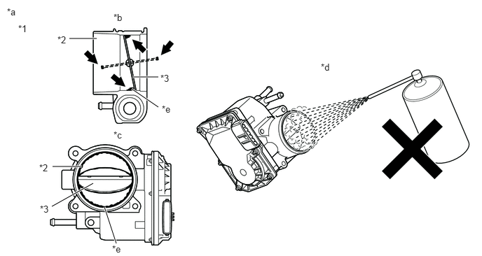
| *1 | Throttle Body with Motor Assembly | *2 | Bore |
| *3 | Valve | - | - |
| *a | Reference | *b | Throttle Body with Motor Assembly Cross-section Diagram |
| *c | When valve fully opened | *d | Do not directly apply cleaner |
| *e | Deposits | - | - |
- NOTICE:
- ·
Make sure that the cloth or your fingers do not get caught in the valve.
·Make sure that foreign matter does not enter the throttle valve.
·Do not directly apply non-residue solvent to the throttle body with motor assembly or wash the throttle body with motor assembly. Cleaning solvent may leak into the motor from the shaft and cause problems such as rust or valve movement problems.
·If there is coating material on the edge of the valve, be careful not to remove it.
- HINT:
-
The illustrations are for reference only. Actual parts may differ.
- Result:
Proceed to NEXT
NEXT
Perform "Inspection After Repair" after cleaning the throttle body with motor assembly.
Connect the GTS to the DLC3.
Turn the ignition switch to ON.
Turn the GTS on.
Start the engine and warm it up until the engine coolant temperature reaches 75°C (167°F) or higher.
Allow the engine to idle for 3 minutes or more and confirm that the engine speed is within the specified range.
- HINT:
-
If the engine is operated without performing learning value reset and idle learning after cleaning the deposits from the throttle body with motor assembly, the idle speed may increase.
- Result:
Proceed to NEXT
NEXT
Perform a spark test.
- HINT:
- ·
If there is a malfunction for a specific cylinder, exchange the ignition coil assembly and spark plug of the malfunctioning cylinder with that of another cylinder and check if the malfunction disappears.
·If the malfunction does not disappear after the ignition coil assembly and spark plug is exchanged or spark does not occur for any cylinder, inspect the ignition circuit.
- Result:
Proceed to NEXT
NEXT
Repair or replace the malfunctioning part.
- HINT:
-
Perform "Inspection After Repair" after repairing or replacing the malfunctioning part.
- Result:
Proceed to NEXT
NEXT
Check that the engine has returned to normal.
- Result:
Proceed to NEXT
NEXT