STOP AND START STOP AND START SYSTEM SYSTEM DESCRIPTION
STOP AND START CONTROL
The stop and start system operates according to the following conditions, achieving appropriate engine stop and start control together with safe and smooth driving characteristics.
When all of the conditions in the following table have been met, the engine is stopped by stop and start control.
| Item | Condition
(All of the following conditions are met) |
|
|---|---|---|
| Idle Stop | Ignition Switch | 5 second or more have passed with the ignition switch ON |
| Engine Coolant Temperature | 40 to 105°C (104 to 221°F) | |
| Ambient Temperature | -5°C (23°F) or higher | |
| Driver Door | 3 seconds have elapsed after driver door closed | |
| Driver Seat Belt | 3 seconds have elapsed after driver seat belt fastened | |
| Brake Booster Vacuum | Vacuum meets the specified condition (42.5 kPa (319 mmHg, 12.6 in.Hg) or more on a level surface) (Brake booster vacuum varies according to brake master oil pressure) | |
| Brake Master Cylinder Fluid Pressure*1 | 1.1 MPa or higher (11.2 kgf/cm2, 160 psi) (changes according to gradient) | |
| Shift Position | After shift lever is operated and 1 second elapses, shift lever is in D | |
| Drive Mode | NORMAL or ECO mode | |
| CVT Fluid Temperature | 25 to 110°C (77 to 230°F) | |
| Stop and Start System Cancel Switch (Eco Run Cancel Switch Assembly) | Off (System control is not prohibited) | |
| Vehicle Speed | 0 km/h (0 mph) (After the engine warms up and having run) | |
| Road Grade | Road Surface Gradient: Road Surface gradient condition is permitted (road surface gradient is within -1.02 m/s2 to 1.36 m/s2) | |
| Engine Speed | 1250 rpm or less | |
| Hood | 3 seconds have elapsed after hood closed | |
| Battery Voltage | When using specified battery:
8.7 V or higher when starter begins operation and 8.3 V or higher when cranking When using non-specified battery:
8.92 V or higher when starter begins operation and 8.92 V or higher when cranking |
|
| Battery Fluid Temperature*2 | -10°C or higher and 55°C or less (14°F or higher and 131°F or less) | |
| Battery Integrated Current*3 | One of the following conditions is met:
·
-4554 A-sec or more: "Status of Battery Charge Control"*4 is Charge Control Coordination Mode, Stop and Start Standalone Mode or Low Temperature Mode ·
0 A-sec or more: "Status of Battery Charge Control"*4 is Stop and Start Restriction Mode or Temperature High/Low Mode |
|
| Idle Stop | Battery Charge Control | The value of Data List item Status of Battery Charge Control*4 is Charge Control Coordination Mode, Stop and Start Standalone Mode, Stop and Start Restriction Mode, Temperature High/Low Mode or Low Temperature Mode |
| Idling Stop Rate / Total Idling Stop Rate | ·
Idling stop rate for one trip: 50% or less (Varies according to battery fluid temperature). ·
Total idling stop rate: Less than 40%
|
|
| Air Conditioning | Any of the following conditions are met:
·
Defogger Switch: OFF, and Blower Switch: OFF ·
With blower switch on, evaporator temperature below threshold (varies depending on each temperature, humidity, amount of solar radiation, etc.) and after certain period of time since engine restarted by stop and start system (threshold varies depending on idling stop conditions) |
|
| Heater | One of the following conditions is met:
·
Blower switch is off ·
While blower switch is on and A/C switch is off, one of the following conditions is met: -
Ambient temperature is higher than 10°C, or -
Engine coolant temperature is higher than 55°C, or -
Vehicle cabin temperature is higher than the set temperature - 5°C ·
While blower switch is on and A/C switch is off, a certain amount of time has elapsed after engine state changed from "not running" to "running". |
|
| Cooler | One of the following conditions is met:
·
Blower switch is off ·
A/C switch is off ·
Ambient temperature 23°C (73°F) or less ·
Evaporator internal temperature less than 9°C (48°F), air mix damper opening value more than 10%, and vehicle cabin temperature less than 3°C (37°F) above set temperature or blower level less than 16 (when ignition switch turned to ON for first time in one trip) |
|
| Steering Wheel | When the steerage angle of the steering wheel is 45 degrees or less. | |
| Engine Control | ·
Engine catalytic warm up is completed ·
Engine control learning has completed ·
Automatic transmission control learning has completed |
|
| Dynamic Radar Cruise Control System | ·
When the dynamic radar cruise control (w/ Full Speed Range Following Function) system is operating and the brake hold function is operating, the preceding vehicle starts off or the user performs a resume operation (starts off the vehicle) ·
When the condition is prohibited by radar cruise control |
|
- HINT:
- ·
*1: Enough brake force is applied to prevent the vehicle from moving when the engine is started again.
·*2: When the battery fluid temperature is -15°C (5°F) or less, or 75°C (167°F) or higher, stop and start control is prohibited. When the battery fluid temperature returns to -10°C (14°F) or higher, and 70°C (158°F) or less, stop and start control is permitted.
·*3: Read the Data List items "Integrated Current" and "Stop&Start Operating Permission (Integrated Current)" when checking the integrated current value
·*4: Please refer to the Data List "Status of Battery Charge Control" for information about the status of the battery charge control.
When the engine is stopped by stop and start control, and any of the following conditions are met, the engine will restart.
| Item | Condition
(Any of the following conditions is met) |
|
|---|---|---|
| Engine Restart | Brake Booster Vacuum | Brake booster vacuum insufficient (Brake booster vacuum changes in accordance with brake fluid pressure (brake pedal effort)) |
| SFI System | Malfunction in SFI system is detected | |
| Power Steering System | Malfunction in power steering system is detected | |
| Vehicle Stability Control System | Malfunction in vehicle stability control system is detected | |
| Oil Pump with Motor Assembly (Continuously Variable Transaxle Assembly) | Oil pump with motor assembly (continuously variable transaxle assembly) malfunctioning | |
| Air Conditioning | Timer in the air conditioning amplifier assembly runs out | |
| Heater | Timer in the air conditioning amplifier assembly runs out | |
| Air Conditioning/Heater | Both of the following conditions are met:
·
Blower switch: ON ·
Evaporator temperature exceeds threshold value (threshold value varies with temperature, humidity and amount of solar radiation) Any of the following conditions are met:
·
A/C switch, blower switch: ON ·
Defogger switch: ON ·
Blower switch turned off during auto control or blower mode changed to manual ·
Changes from stop and start system priority control to normal system control |
|
| Battery | Battery voltage drops (11.8 V or less) | |
| Battery Integrated Current* | The accumulated value of discharge current during engine stop is too large (2376 A-sec or more) | |
| Battery Fluid Temperature | -15°C or higher and 60°C or less (5°F or higher and 140°F or less) | |
| Vehicle Speed | Vehicle speed signal is input (Vehicle stopped on a slope, etc.) | |
| Driver Door | Open | |
| Driver Seat Belt | Driver seat belt is unfastened | |
| Steering Wheel | Steering wheel turned 25 degrees or more | |
| Brake Pedal | Brake pedal released ( But, engine does not restart if brake hold system operate even though driver release the brake pedal.) | |
| Accelerator Pedal | Accelerator pedal is depressed | |
| Shift Position | Move the shift lever from D to other position | |
| Stop and Start System Cancel Switch (Eco Run Cancel Switch Assembly) | When stop and start system cancel switch (eco run cancel switch assembly) turn from off to on | |
| Drive Mode | except NORMAL and ECO mode | |
| Dynamic Radar Cruise Control System | ·
A vehicle stops during ACC control system operate state, and after the precedent vehicle move or driver do resume operation (operation to move) ·
When the condition is prohibited by radar cruise control |
|
- HINT:
*: Read the Data List items "Integrated Current" and "Stop&Start Operating Permission (Integrated Current)" when checking the integrated current value
SYSTEM PROHIBITION CONTROL
The engine stop and start ECU prohibits stop and start control by the stop and start system according to the table below. The prohibition conditions are specified for each system.
| System | Prohibition Condition | Vehicle State | Restoration Condition | Prohibition Condition Check Timing |
|---|---|---|---|---|
| Engine | Engine coolant temperature less than 40°C (104°F) | Engine has not warmed up | Engine coolant temperature 40 to 105°C (104 to 221°F) | Always |
| Idle speed learning has not completed | Stop and start control prohibited until idle speed learning completes | Idle speed learning has completed | Always | |
| Engine catalytic warm up | Engine catalytic warm up is being performed | Engine catalytic warm up is completed | Each time engine is started or vehicle is stopped | |
| Brake | Brake booster vacuum decreases | Brake booster vacuum decreases due to pumping the brakes, etc. | Normal brake booster vacuum is reached | Every time the vehicle stops |
| Brake master cylinder fluid pressure decreases | Brake pedal depressed lightly | Brake pedal depressed more | Every time the vehicle stops | |
| Hill-start Assist Control | Brake control system malfunction | DTC detected | Brake control system returns normally | Always |
| When hill-start assist control prohibition is necessary | Vehicle speed is 3 km/h (1.8 mph) or more | Vehicle is being stopped (vehicle speed is below 3 km/h (1.8 mph)) | Always | |
| Communication between engine stop and start ECU and skid control ECU (brake actuator assembly) is invalid | Communication invalid | Communication between engine stop and start ECU and skid control ECU (brake actuator assembly) is valid | Always | |
| Gradient of Road Surface | Outside the permitted gradient range (road surface gradient is within more than 1.36 m/s2 or less than -1.02 m/s2) | Road surface gradient is within more than 1.36 m/s2 or less than -1.02 m/s2 | Within the permitted gradient range (road surface gradient is within -1.02 m/s2 to 1.36 m/s2) | Always |
| Air Conditioning | Heater:
All of the following conditions are met:
·
Blower switch is on ·
Ambient temperature 10°C (50°F) or less ·
One of the following conditions is met: -
Engine coolant temperature 55°C (131°F) or less -
Cabin temperature lower than set temperature by -5°C (-9°F) or less (only standard control (NORMAL) mode) |
Heater performance decreases | ·
Actual temperature higher than target temperature ·
Blower switch off |
While the heater is on |
| Cooling function:
When blower switch and A/C switch is on and ambient temperature 23°C (73.4°F) or higher, either of the following conditions is met:
·
Evaporator temperature 9°C (48.2°F) or higher ·
Cabin temperature higher than set temperature by 3°C (5°F) or higher, or blower level 16 or higher (only standard control (NORMAL) mode) |
Cooling performance decreases | Any of the following condition shave been met:
1.
Actual temperature higher than target temperature 2.
Blower switch is off 3.
Air conditioning switch is off |
While the air conditioning system (cooling function) is on | |
| Defogger:
Both of the following conditions are met:
·
Defogger switch on ·
Blower switch on |
Fogging of windows | Defogger switch or blower switch off | Always | |
| Temporary stop and start control:
All of the following conditions are met:
·
Blower switch on ·
Evaporator temperature exceeds threshold (threshold varies with temperature, humidity and amount of solar radiation) ·
Certain amount of time has elapsed after the engine is stopped by stop and start control (threshold value varies with stop and start operation conditions) |
Blower switch on | Blower switch off and evaporator temperature within specified range | Always | |
| Driver Door | Driver door opened before engine stop by engine stop and start control | Driver door courtesy switch ON signal input | 3 seconds have elapsed since driver door was closed | Always |
| Engine Hood | Engine hood opened before engine stop by stop and start control | Engine hood switch off signal input | 3 seconds have passed since engine hood was closed | Always |
| Seat Belt | Driver seat belt not fastened before engine stop by engine stop and start control | Driver seat belt buckle switch off signal input | 3 seconds have passed since driver seat belt was fastened | Always |
| Steering Wheel | Steering wheel turned at a speed of 45 deg/s or more | Steering wheel operation signal input | Steering wheel being held | Always |
| Continuously Variable Transaxle Assembly | CVT fluid temperature: Below 25°C (77°F) or 110°C (230°F) or higher | CVT fluid temperature signal input | Permission CVT fluid temperature range reached | Always |
| Shift Position | Shift lever in other than D | Shift position signal input | Brake pedal depressed and shift lever in D | Always |
| Drive Mode | Drive mode is other than ECO and NORMAL mode | Drive mode signal input | Drive mode is ECO or NORMAL mode | Always |
| Ambient Temperature | Ambient temperature -6°C (21.2°F) or lower | - | Ambient temperature -5°C (23°F) or higher | Always |
| Power Source | When using specified battery:
Below 8.5 V when starter begins operation and below 8.3 V when cranking When using non-specified battery:
Below 8.92 V when starter begins operation and below 8.92 V when cranking |
Battery charge insufficient or battery has deteriorated | Battery charged or replaced*
*: When prohibited, the prohibition condition continues until the ignition switch is turned off |
Every time the engine is started |
| Battery fluid temperature -15°C (5°F) or less, or 60°C (140°F) or higher | Depends on environmental temperature | Battery fluid temperature is reached (-10°C (14°F) or higher and 55°C (131°F) or less) | Always | |
Battery integrated current*1 value meets one of the following conditions:
·
-16434 A-sec or less: "Status of Battery Charge Control"*2 is Charge Control Coordination Mode, Stop and Start Standalone Mode, Low Temperature Mode or Temperature High/Low Mode ·
-990 A-sec or less: "Status of Battery Charge Control"*2 is Stop and Start Restriction Mode |
·
Heavy electrical load ·
High stop and start rate (Time that engine stopped by stop and start control is long) |
Battery integrated current*1 value meets one of the following conditions:
·
-4554 A-sec or more: "Status of Battery Charge Control"*2 is Charge Control Coordination Mode, Stop and Start Standalone Mode or Low Temperature Mode ·
0 A-sec or higher: "Status of Battery Charge Control"*2 is Stop and Start Restriction Mode or Temperature High/Low Mode |
Always | |
| During refresh charge | ·
Cable reconnected to battery terminal ·
Refresh charge is performed for 30 minutes or more for every 30 hours of driving |
·
Cable reconnected to battery terminal: 5 to 60 minutes ·
Periodic refresh charge: 30 to 60 minutes |
Always | |
| Engine started with the engine hood open | - | After ignition switch is turned off, ignition switch is turned to ON with hood closed | Every time the engine is started | |
| Idling Stop Rate | ·
Idling stop rate for one trip: 50% or less (Varies according to battery fluid temperature). ·
Total idling stop rate: Less than 40%
|
Vehicle is frequently stopped | Idling stop rate has decreased due to vehicle being driven and engine idling | Always |
- HINT:
- ·
*1: Read the Data List items "Integrated Current" and "Stop&Start Operating Permission (Integrated Current)" when checking the integrated current value.
·*2: Please refer to the Data List "Status of Battery Charge Control" for information about the status of the battery charge control.
·If the cable is disconnected from the battery terminal, stop and start control is prohibited until refresh charge is completed.
In this case, let the vehicle idle to complete the refresh charge. The refresh charge is complete when the Data List item Status of Battery Charge Control changes from "Refresh Charge Mode". (Usually, idling the engine for 5 to 60 minutes with the battery fluid temperature at 11°C (51°F) or higher, the refresh charge will be completed.)
·If the GTS is not available and the Data List item Status of Battery Charge Control cannot be checked, charge the battery by idling the engine for approximately 5 to 60 minutes or driving the vehicle, and then drive the vehicle and check that stop and start control operates.
If the engine is started with the hood open, the system determines that a jump start has occurred. Therefore, make sure that the hood is closed before starting the engine and driving the vehicle.
·After the refresh charge completes, turn the ignition switch off, wait for at least 30 seconds, and then start the engine again. If the vehicle enters refresh charge mode again while the engine is idling, the initial refresh charge did not properly complete, so wait for the refresh charge to complete.
·Allow the engine to idle for 3 minutes after it is warmed up and check that the engine idle speed is within 50 rpm of the target idle speed.
WARNING CONTROL
If any of the following operations are performed while the engine is stopped due to stop and start control, the system will not restart the engine. The engine will change the mode from "stopped due to system control" to "stalled" or the driver will be warned using the buzzer.
| Operation | Warning Control |
|---|---|
| The engine hood is opened with the shift lever in D | The engine stops (mode changes to "stalled", and the engine cannot be restarted until the ignition switch is turned off and then to ON) |
| The driver door is opened with the shift lever in D | The engine starts, warning buzzer sounds and stop and start indicator blinks |
| The driver seat belt is unfastened | The engine starts |
WARNING INDICATOR AND BUZZER OPERATION
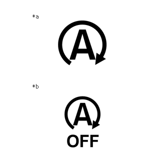
| *a | Stop and Start Indicator |
| *b | Stop and Start Cancel Indicator |
The driver is informed of the system control status and warnings by the stop and start indicator, stop and start cancel indicator and the buzzer.
| Item | Condition | Stop and Start Indicator
(Green) |
Stop and Start Cancel Indicator
(Orange) |
Buzzer |
|---|---|---|---|---|
| For 3 seconds after the ignition switch to ON | Normal operation | Does not come on | Comes on | Does not sound |
| During stop and start control operation (engine is stopped) | Normal operation | Comes on | Does not come on | Does not sound |
| Driver door opened | The blinking interval 0.15 seconds* | Does not come on | Sounds* | |
| After engine started by stop and start control | Driver door opened within 5 seconds of engine start | The blinking interval 0.15 seconds* | Does not come on | Sounds* |
| Control is prohibited by the stop and start system cancel switch (eco run cancel switch assembly) | Normal operation | Does not come on | Comes on | Does not sound |
| Diagnostic trouble code | Any DTCs are stored | Does not come on | The blinking interval 0.5 seconds | Does not sound |
| Starter assembly life | Number of times the starter has been operated exceeds its limit | Does not come on | The blinking interval 0.5 seconds | Does not sound |
*: Shift lever in D
MULTI-INFORMATION DISPLAY MESSAGE AND INDICATOR OPERATION
An indicator and/or messages are displayed on the multi-information display to indicate condition of the stop and start system when certain vehicle conditions are met.
| Stop and Start System Condition | Multi-information Display Message*1 | Vehicle Condition | |
|---|---|---|---|
| When the engine cannot be stopped by the stop and start system | 
*2 |
"Non-Dedicated Battery" | A non-specified battery for the stop and start system may have been installed. |
| "Battery Charging" | ·
The battery charge amount may be low. ·
The battery voltage is low ·
The battery fluid temperature is high ·
A refresh charge may be occurring. |
||
| "Stop & Start System Unavailable" | ·
The Stop & Start System is temporarily disabled. ·
The engine may have been started with the hood opened. |
||
| "In Preparation" | ·
The vehicle is being driven in a high altitude area. ·
The brake booster vacuum is low. |
||
| "For Climate Control" | ·
The air conditioning system is being used when the ambient temperature is high or low. ·
Windshield defogger is pressed. |
||
| "Press Brake More to Active" | The brake pedal is not depressed enough. | ||
| When the engine automatically restarts while stopped by the stop and start system |
*2 |
"In Preparation" | The brake pedal is strongly depressed further or pumped. |
| "For Climate Control" | ·
The air conditioning system is turned on or the air conditioning is being used. ·
Windshield defogger is turned on. |
||
| "Battery Charging" | The battery charge amount may be low. | ||
| The system may be malfunctioning | - | "Stop & Start System Malfunction Visit Your Dealer" | - |
- HINT:
- ·
*1: Messages are listed in the order of priority.
·*2: When the engine cannot be stopped by the stop and start system or the engine is restarted while the engine is stopped by the stop and start system, the following mark is displayed on the multi-information display.
STOP AND START SYSTEM OPERATION
Depending on the type of malfunction, stop and start control may be prohibited by the fail-safe function. The following table shows effects on the vehicle and areas to be inspected when there is a malfunction in the stop and start system.
| Malfunctioning Area | Malfunction | DTC Output | Data List / Freeze Frame Data | Effect on Vehicle | Area to be Inspected |
|---|---|---|---|---|---|
| IGP circuit | Open | P253014 | IG Switch | ·
Stop and start control prohibited ·
Engine is automatically restarted if a DTC is stored while the engine is stopped by stop and start control |
Wire harness or connector |
| +B circuit | Open | - | Data List cannot be checked because power not supplied to the engine stop and start ECU | Stop and start control prohibited | Wire harness or connector |
| BNT1 (engine hood courtesy switch) circuit | Stuck on | - | Hood Courtesy Switch | Mode does not change to "stalled" when engine hood opened with shift lever in D and engine stopped by stop and start control | ·
Wire harness or connector ·
Engine hood courtesy switch (hood lock assembly) |
| Stuck off | - | Stop and start control prohibited despite engine hood being closed | |||
| ECAN (stop and start system cancel switch (eco run cancel switch assembly)) circuit | Stuck on | - | Stop&Start Cancel Switch | Stop and start control prohibited | ·
Wire harness or connector ·
Stop and start system cancel switch (eco run cancel switch assembly) |
| Stuck off | - | Stop and start control cannot be canceled by pressing the stop and start system cancel switch (eco run cancel switch assembly) | |||
| BRVC/PB/BRE2 (vacuum sensor) circuit | Open | P055515 | Brake Boost Pressure | ·
Stop and start control prohibited ·
Engine is automatically restarted if a DTC is stored while the engine is stopped by stop and start control ·
Stop and start cancel indicator blinks |
·
Wire harness or connector ·
Vacuum sensor assembly ·
Brake booster assembly ·
Vacuum hose |
| Shorted | ·
P055511 ·
P055515 |
||||
| Remains at intermediate value | ·
P055500 ·
P05552A |
||||
| NOPM circuit
OPM1 circuit OP21 circuit (Oil pump with motor assembly) |
·
Open ·
Shorted ·
Internal circuit malfunction |
·
P0C2B11 ·
P0C2B15 ·
P279796 |
·
Oil Pump Relay ·
Oil Pump Duty ·
State of Oil Pump Motor Revolution ·
Oil Pump Motor Revolution Frequency |
·
Stop and start control prohibited ·
Engine is automatically restarted if a DTC is stored while the engine is stopped by stop and start control ·
Stop and start cancel indicator blinks |
·
Wire harness or connector ·
Engine stop and start ECU ·
Oil pump with motor assembly |
| Oil pump with motor assembly | Oil pump with motor assembly malfunction | P094296 | Stop&Start Operating Permission (AT/CVT) | ·
Stop and start control prohibited ·
Engine is automatically restarted if a DTC is stored while the engine is stopped by stop and start control ·
Stop and start cancel indicator blinks |
Oil pump with motor assembly |
| STA circuit | Overcurrent | P061511 | - | ·
Stop and start control prohibited ·
Stop and start cancel indicator blinks |
·
BBC NO. 1 fuse ·
BBC NO. 2 fuse ·
Wire harness or connector ·
ST NO. 1 relay ·
Engine stop and start ECU |
| Stuck on | P0A1E00 | ·
Wire harness or connector ·
ST NO. 1 relay ·
Engine stop and start ECU |
|||
| Stuck off | P0A1E00 | ||||
| BBC (backup boost converter) circuit | Overcurrent | X087A | State of BBC | ·
Stop and start control prohibited ·
Stop and start cancel indicator blinks |
·
BBC NO. 1 fuse ·
BBC NO. 2 fuse ·
Wire harness or connector ·
Engine stop and start ECU ·
Battery ·
ECUs and sensors connected to B41, B42, B43 and IG41 |
·
Open ·
Shorted ·
Internal circuit malfunction ·
Battery |
·
P323A00 ·
P323A16 ·
P323B14 ·
P323B29 ·
P323B38 |
State of BBC | ·
Stop and start control prohibited ·
Engine is automatically restarted if a DTC is stored while the engine is stopped by stop and start control ·
Stop and start cancel indicator blinks |
·
BBC NO. 1 fuse ·
BBC NO. 2 fuse ·
Wire harness or connector ·
Engine stop and start ECU ·
Battery |
|
| Monitoring CPU circuit | Malfunction | P060629 | State of BBC | ·
Stop and start control prohibited ·
Engine is automatically restarted if a DTC is stored while the engine is stopped by stop and start control ·
Stop and start cancel indicator blinks |
Engine stop and start ECU |
| Malfunctioning Area | Malfunction | DTC Output | Data List / Freeze Frame Data | Effect on Vehicle | Area to be Inspected |
|---|---|---|---|---|---|
| SFI system | MIL illuminated | DTCs for SFI system output | ·
Stop&Start Operating Permission (ECM 1) ·
Stop&Start Operating Permission (ECM 2) |
Stop and start control prohibited | SFI system |
| Abnormal NE signal | DTCs for SFI system output | - | ·
Stop and start control prohibited ·
Stop and start cancel indicator blinks |
·
SFI system (crankshaft position sensor circuit) ·
Wire harness or connector |
|
| Crankshaft reverse rotation detection | DTCs for SFI system output | - | ·
Stop and start control prohibited ·
MIL illuminated |
SFI system (crankshaft position sensor circuit) | |
| Charging system | Battery state sensor assembly malfunction | Charging system DTCs output | ·
Battery Fluid Temperature ·
Integrated Current |
Stop and start control prohibited | Charging system |
| Vehicle stability control system | Vehicle stability control running | - | ABS Running | Stop and start control prohibited | - |
| Malfunction in wheel speed sensor | Brake control system DTCs output | ·
Vehicle Speed ·
Wheel Speed Malfunction |
Stop and start control prohibited | ·
Wire harness or connector ·
Skid control ECU (Brake actuator assembly) ·
Vehicle speed sensor |
|
| Power steering system | Malfunction in power steering system | EPS assist current value invalid | ·
EPS Load ·
EPS Assist Current Available |
Stop and start control prohibited | ·
Power steering ECU (Rack and pinion power steering gear assembly) ·
Torque sensor |
| Seat belt warning system | Malfunction in seat belt warning system | - | Driver Seat Belt Buckle Switch | ·
Stop and start control prohibited (stuck off) ·
Engine does not restart when it is stopped by stop and start control (stuck on) |
·
Front seat inner belt assembly LH ·
Wire harness or connector |
| Driver door courtesy light switch circuit | Malfunction in driver door courtesy light switch circuit | - | Driver Courtesy Switch Signal | ·
Stop and start control prohibited (stuck off) ·
Engine does not restart when it is stopped by stop and start control (stuck on) ·
Stop and start indicator blinks ·
Sounds the warning buzzer |
·
Front door courtesy light switch assembly (for driver side) ·
Driver door courtesy light switch circuit |
| Air conditioning system | Malfunction in ambient temperature sensor | Air conditioning system DTCs output | Ambient Temperature | Stop and start control prohibited | Ambient temperature sensor circuit |
| Brake vacuum | Brake booster vacuum drops | - | ·
Brake Boost Pressure ·
Brake Negative Pressure |
Stop and start control prohibited | ·
Brake booster assembly vacuum ·
Brake booster assembly ·
Vacuum sensor assembly ·
Vacuum hose |
| Power source | Backup boost converter malfunction | ·
P323A00 ·
P323A16 ·
P323B14 ·
P323B29 ·
P323B38 |
State of BBC | ·
Stop and start control prohibited ·
Engine is automatically restarted if a DTC is stored while the engine is stopped by stop and start control ·
Stop and start cancel indicator blinks |
·
BBC NO. 1 fuse ·
BBC NO. 2 fuse ·
Wire harness or connector ·
Engine stop and start ECU ·
Battery |
| Charging system malfunction | - | Alternator Status | Stop and start control prohibited | Charging system | |
| Charging control system | X0879 | - | ·
Stop and start control prohibited |
Charging system | |
| Number of starter operations | Exceeds the specified limit | X0877 | ·
Starter Operation # ·
Number of Engine Starts (IG-ON) ·
Number of Engine Starts (Stop & Start) |
·
Stop and start control prohibited ·
Stop and start cancel indicator blinks |
·
Starter assembly replacement is required ·
ST NO. 1 relay replacement is required ·
Fuse replacement is required |
| Starter signal malfunction | Signal does not match with the starter switch | P061515 | ·
Starter ·
Starter Motor ·
Engine Starter Signal |
·
Stop and start control prohibited ·
Stop and start cancel indicator blinks |
·
Wire harness or connector ·
Engine stop and start ECU |
| Jump start | Engine started with the engine hood open | - | Stop&Start Operating Prohibition (Jump Start) | Stop and start control prohibited
(permitted when the ignition switch is turned off) |
·
Check for history of roadside service or jump start due to dead battery ·
Engine hood courtesy switch (hood lock assembly) |
| CAN communication | Communication interrupted | ·
U010087 ·
U012687 ·
U012987 ·
U014087 ·
U015187 ·
U015587 ·
U016487 ·
U117087 |
- | ·
Stop and start control prohibited ·
Engine is automatically restarted if a DTC is stored while the engine is stopped by stop and start control ·
Stop and start cancel indicator blinks |
·
Applicable wire harness or connector ·
Applicable ECU |