NETWORKING LIN COMMUNICATION SYSTEM(for GTMC Made) B120687 P/W Master SW System Missing Message B127387 Sliding Roof System Missing Message B232187 D-Door P/W System Missing Message B232287 P-Door P/W System Missing Message B232387 RR-Door P/W System Missing Message B232487 RL-Door P/W System Missing Message
DESCRIPTION
This DTC is stored when LIN communication between the main body ECU (multiplex network body ECU) and multiplex network master switch assembly, front power window regulator motor assembly LH, frontpower window regulator motor assembly RH, rear power window regulator motor assembly RH, rearpower window regulator motor assembly LH or sliding roof ECU (sliding roof drive gear assembly)* stopsfor 10 seconds or more.
*: w/ Sliding Roof System, Panoramic Moon Roof System
| DTC No. | Detection Item | DTC Detection Condition | Trouble Area |
|---|---|---|---|
| B120687 | P/W Master SW System Missing Message | No communication between multiplex network master switch assembly and main body ECU (multiplex network body ECU) for 10 seconds or more. | ·
Main body ECU (multiplex network body ECU) ·
Power distribution box assembly ·
Multiplex network master switch assembly ·
Harness or connector |
| B127387 | Sliding Roof System Missing Message | No communication between sliding roof ECU (sliding roof drive gear sub-assembly) and main body ECU (multiplex network body ECU) for 10 seconds or more. | ·
Main body ECU (multiplex network body ECU) ·
Power distribution box assembly ·
Sliding roof ECU (sliding roof drive gear assembly) (w/ Sliding Roof System, Panoramic Moon Roof System) ·
Harness or connector |
| B232187 | D-Door P/W System Missing Message | No communication between front power window regulator motor assembly LH and main body ECU (multiplex network body ECU) for 10 seconds or more. | ·
Main body ECU (multiplex network body ECU) ·
Power distribution box assembly ·
Multiplex network master switch assembly ·
Front power window regulator motor assembly LH ·
Harness or connector |
| B232287 | P-Door P/W System Missing Message | No communication between front power window regulator motor assembly RH and main body ECU (multiplex network body ECU) for 10 seconds or more. | ·
Main body ECU (multiplex network body ECU) ·
Power distribution box assembly ·
Front power window regulator motor assembly RH ·
Harness or connector |
| B232387 | RR-Door P/W System Missing Message | No communication between rear power window regulator motor assembly RH and main body ECU (multiplex network body ECU) for 10 seconds or more. | ·
Main body ECU (multiplex network body ECU) ·
Power distribution box assembly ·
Rear power window regulator motor assembly RH ·
Harness or connector |
| B232487 | RL-Door P/W System Missing Message | No communication between rear power window regulator motor assembly LH and main body ECU (multiplex network body ECU) for 10 seconds or more. | ·
Main body ECU (multiplex network body ECU) ·
Power distribution box assembly ·
Rear power window regulator motor assembly LH ·
Harness or connector |
WIRING DIAGRAM
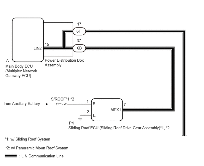
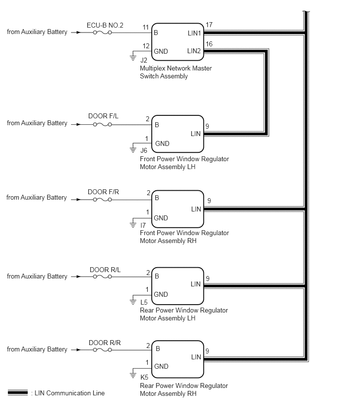
CAUTION / NOTICE / HINT
- NOTICE:
- ·
Inspect the fuses for circuits related to this system before performing the following procedure.
·Some parts must be initialized and set when replacing or removing and installing parts.
PROCEDURE
Clear the DTCs.
- Body Electrical > Main Body > Clear DTCs
- 50002 449
Check for DTCs.
- Body Electrical > Main Body > Trouble Codes
- 50001 449
- Result:
Result Proceed to *: w/ Sliding Roof System, Panoramic Moon Roof System
DTC B235288 is output A DTC B120687, B127387*, B232187, B232287, B232387 and B232487 are all output B Within DTC B120687, B127387*, B232187, B232287, B232387 and B232487, one or more DTCs are output C DTC is not output D
A
B
C
D
Remove the power distribution box assembly.
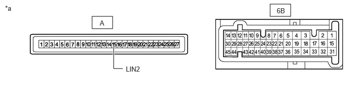
| *a | Component without harness connected
(Power Distribution Box Assembly) |
- | - |
Remove the main body ECU (multiplex network body ECU) from the power distribution box assembly.
Measure the resistance according to the value(s) in the table below.
- Standard Resistance:
Tester Connection Condition Specified Condition 6B-37 - A-15 (LIN2) Always Below 1 Ω
- Result:
Proceed to OK NG
OK
NG
Check for DTCs.
- Body Electrical > Main Body > Trouble Codes
- 50001 449
- Result:
Result Proceed to *: w/ Sliding Roof System, Panoramic Moon Roof System
DTCs B120687, B232187, B232287, B232387 and B232487 are output A DTCs B120687 and B232187 are output B Only DTC B120687 is output C Only DTC B127387 is output* D Only DTC B232187 is output E Only DTC B232287 is output F Only DTC B232387 is output G Only DTC B232487 is output H
A
B
C
D
E
F
G
H
Disconnect the 6F power distribution box assembly connector.
Disconnect the J2 multiplex network master switch assembly connector.
Measure the resistance according to the value(s) in the table below.
- Standard Resistance:
Tester Connection Condition Specified Condition 6F-17 - J2-17 (LIN1) Always Below 1 Ω
- Result:
Proceed to OK NG
OK
NG
Disconnect the 6F power distribution box assembly connector.
Disconnect the J2 multiplex network master switch assembly connector.
Measure the resistance according to the value(s) in the table below.
- Standard Resistance:
Tester Connection Condition Specified Condition 6F-17 - J2-17 (LIN1) Always Below 1 Ω
- Result:
Proceed to OK NG
NG
OK
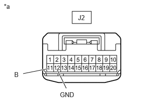
| *a | Front view of wire harness connector
(to Multiplex Network Master Switch Assembly) |
Disconnect the multiplex network master switch assembly connector.
Measure the voltage according to the value(s) in the table below.
- Standard Voltage:
Tester Connection Switch Condition Specified Condition J2-11 (B) - Body ground Ignition switch off 11 to 14 V
Measure the resistance according to the value(s) in the table below.
- Standard Resistance:
Tester Connection Condition Specified Condition J2-12 (GND) - Body ground Always Below 1 Ω
- Result:
Proceed to OK NG
OK
NG
Remove the power distribution box assembly.
| *a | Component without harness connected
(Power Distribution Box Assembly) |
- | - |
Remove the main body ECU (multiplex network body ECU) from the power distribution box assembly.
Measure the resistance according to the value(s) in the table below.
- Standard Resistance:
Tester Connection Condition Specified Condition 6B-37 - A-15 (LIN2) Always Below 1 Ω
- Result:
Proceed to OK NG
OK
NG
Disconnect the 6B power distribution box assembly connector.
Disconnect the P4 sliding roof ECU (sliding roof drive gear assembly) connector.
Measure the resistance according to the value(s) in the table below.
- Standard Resistance:
Tester Connection Condition Specified Condition 6B-37 - P4-7 (MPX1) Always Below 1 Ω
- Result:
Proceed to OK NG
NG
OK
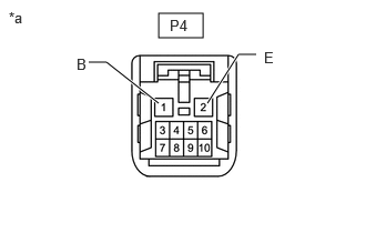
| *a | Front view of wire harness connector
(to Sliding Roof ECU [Sliding Roof Drive Gear Assembly]) |
Disconnect the sliding roof ECU (sliding roof drive gear assembly) connector.
Measure the voltage according to the value(s) in the table below.
- Standard Voltage:
Tester Connection Switch Condition Specified Condition P4-1 (B) - Body ground Ignition switch off 11 to 14 V
Measure the resistance according to the value(s) in the table below.
- Standard Resistance:
Tester Connection Condition Specified Condition P4-2 (E) - Body ground Always Below 1 Ω
- Result:
Proceed to OK NG
OK
w/ Panoramic Moon Roof System: Click hereVehicle Exterior>SLIDING ROOF / CONVERTIBLE>SLIDING ROOF HOUSING (for Panoramic Moon Roof)>REMOVAL202405,202409,_59,_083108,_0400984,RM100000002LTQ2,202409,999999,_59,_083108,_0400984,RM100000002NW8P,
w/ Sliding Roof System: Click hereVehicle Exterior>SLIDING ROOF / CONVERTIBLE>SLIDING ROOF HOUSING (for Moon Roof)>REMOVAL202405,202409,_59,_083108,_0400985,RM100000002LTQ5,202409,999999,_59,_083108,_0400985,RM100000002NW8R,
NG
Disconnect the 6F power distribution box assembly connector.
Disconnect the J6 front power window regulator motor assembly LH connector.
Measure the resistance according to the value(s) in the table below.
- Standard Resistance:
Tester Connection Condition Specified Condition 6F-17 - J6-9 (LIN) Always Below 1 Ω
- Result:
Proceed to OK NG
OK
NG
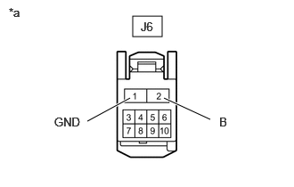
| *a | Front view of wire harness connector
(to Front Power Window Regulator Motor Assembly LH) |
Disconnect the front power window regulator motor assembly LH connector.
Measure the voltage according to the value(s) in the table below.
- Standard Voltage:
Tester Connection Switch Condition Specified Condition J6-2 (B) - Body ground Ignition switch off 11 to 14 V
Measure the resistance according to the value(s) in the table below.
- Standard Resistance:
Tester Connection Condition Specified Condition J6-1 (GND) - Body ground Always Below 1 Ω
- Result:
Proceed to OK NG
OK
NG
Disconnect the J2 multiplex network master switch assembly connector.
Disconnect the J6 front power window regulator motor assembly LH connector.
Measure the resistance according to the value(s) in the table below.
- Standard Resistance:
Tester Connection Condition Specified Condition J2-16 (LIN2) - J6-9 (LIN) Always Below 1 Ω
- Result:
Proceed to OK NG
OK
NG
Disconnect the 6F power distribution box assembly connector.
Disconnect the I7 front power window regulator motor assembly RH connector.
Measure the resistance according to the value(s) in the table below.
- Standard Resistance:
Tester Connection Condition Specified Condition 6F-17 - I7-9 (LIN) Always Below 1 Ω
- Result:
Proceed to OK NG
OK
NG
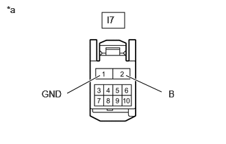
| *a | Front view of wire harness connector
(to Front Power Window Regulator Motor Assembly RH) |
Disconnect the front power window regulator motor assembly RH connector.
Measure the voltage according to the value(s) in the table below.
- Standard Voltage:
Tester Connection Switch Condition Specified Condition I7-2 (B) - Body ground Ignition switch off 11 to 14 V
Measure the resistance according to the value(s) in the table below.
- Standard Resistance:
Tester Connection Condition Specified Condition I7-1 (GND) - Body ground Always Below 1 Ω
- Result:
Proceed to OK NG
OK
NG
Disconnect the 6F power distribution box assembly connector.
Disconnect the K5 rear power window regulator motor assembly RH connector.
Measure the resistance according to the value(s) in the table below.
- Standard Resistance:
Tester Connection Condition Specified Condition 6F-17 - K5-9 (LIN) Always Below 1 Ω
- Result:
Proceed to OK NG
OK
NG
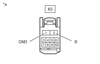
| *a | Front view of wire harness connector
(to Rear Power Window Regulator Motor Assembly RH) |
Disconnect the rear power window regulator motor assembly RH connector.
Measure the voltage according to the value(s) in the table below.
- Standard Voltage:
Tester Connection Switch Condition Specified Condition K5-2 (B) - Body ground Ignition switch off 11 to 14 V
Measure the resistance according to the value(s) in the table below.
- Standard Resistance:
Tester Connection Condition Specified Condition K5-1 (GND) - Body ground Always Below 1 Ω
- Result:
Proceed to OK NG
OK
NG
Disconnect the 6F power distribution box assembly connector.
Disconnect the L5 rear power window regulator motor assembly LH connector.
Measure the resistance according to the value(s) in the table below.
- Standard Resistance:
Tester Connection Condition Specified Condition 6F-17 - L5-9 (LIN) Always Below 1 Ω
- Result:
Proceed to OK NG
OK
NG
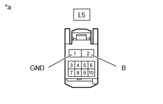
| *a | Front view of wire harness connector
(to Rear Power Window Regulator Motor Assembly LH) |
Disconnect the rear power window regulator motor assembly LH connector.
Measure the voltage according to the value(s) in the table below.
- Standard Voltage:
Tester Connection Switch Condition Specified Condition L5-2 (B) - Body ground Ignition switch off 11 to 14 V
Measure the resistance according to the value(s) in the table below.
- Standard Resistance:
Tester Connection Condition Specified Condition L5-1 (GND) - Body ground Always Below 1 Ω
- Result:
Proceed to OK NG
OK
NG