AXLE AND DIFFERENTIAL REAR DIFFERENTIAL CARRIER ASSEMBLY(for Torque Vectoring Differential) REMOVAL
CAUTION / NOTICE / HINT
The necessary procedures (adjustment, calibration, initialization, or registration) that must be performed after parts are removed and installed, or replaced during torque vectoring differential carrier assembly removal/installation are shown below.
| Replaced Part or Performed Procedure | Necessary Procedure | Effect/Inoperative Function when Necessary Procedure not Performed | Link |
|---|---|---|---|
| Electro magnetic control coupling sub-assembly | ·
ECU data save ·
ECU data initialization ·
ECU data write |
Dynamic torque vectoring AWD system | ( 201910,999999,_52,_083068,_0401882,RM100000001JEAV,) 201910,999999,_52,_083068,_0401882,RM100000001JEAV,)
|
| Rear electro magnetic control clutch sub-assembly (rear differential carrier assembly) | Disconnect system function check | ||
| Suspension, tires, etc. | Parking assist ECU initialization | Panoramic View Monitor System (for Gasoline model) | (202304,999999,_56,_083082,_0586733,RM1000000029R9F,)
|
PROCEDURE

 1.DRAIN DIFFERENTIAL OIL
37100
2.REMOVE PROPELLER SHAFT WITH CENTER BEARING ASSEMBLY
3.REMOVE REAR STABILIZER BAR
77606
4.REMOVE NO. 1 FUEL TANK PROTECTOR
42330
5.REMOVE REAR DRIVE SHAFT ASSEMBLY LH
42330
6.REMOVE REAR DRIVE SHAFT ASSEMBLY RH
- HINT:
-
Use the same procedure described for the LH side.
7.DISCONNECT CABLE FROM NEGATIVE BATTERY TERMINAL
8.REMOVE REAR SEAT ASSEMBLY
73705
9.REMOVE CHILD RESTRAINT SEAT ANCHOR BRACKET SUB-ASSEMBLY RH
58410B
10.REMOVE DECK BOARD ASSEMBLY
58417H
11.REMOVE REAR NO. 3 FLOOR BOARD
58386
12.REMOVE REAR FLOOR FINISH PLATE
58577E
13.REMOVE REAR NO. 1 FLOOR MAT SUPPORT SIDE PLATE
62332C
14.REMOVE REAR DOOR OPENING TRIM WEATHERSTRIP LH
62552F
15.REMOVE REAR SEAT SIDE GARNISH LH
73708A
16.REMOVE TETHER ANCHOR BRACKET SET
58460D
17.REMOVE LUGGAGE HOLD BELT STRIKER ASSEMBLY
64740E
18.REMOVE DECK TRIM SIDE PANEL ASSEMBLY LH
52391B
19.REMOVE DIFFERENTIAL SUPPORT
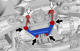
Remove the 4 bolts, 2 nuts and differential support from the rear No. 2 differential support and torque vectoring differential carrier assembly.

Temporarily install the 2 bolts and 2 nuts.
20.REMOVE TORQUE VECTORING DIFFERENTIAL CARRIER ASSEMBLY
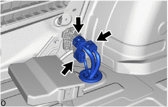
Disconnect the 3 connectors.
Remove the grommet of the frame wire and pass the connector through the hole to the outside of the vehicle.
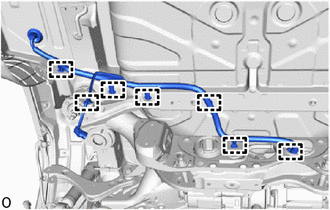
Disengage the 7 wire harness clamps to separate the frame wire.
Support the torque vectoring differential carrier assembly with 2 attachments or equivalent tools as shown in the illustration.
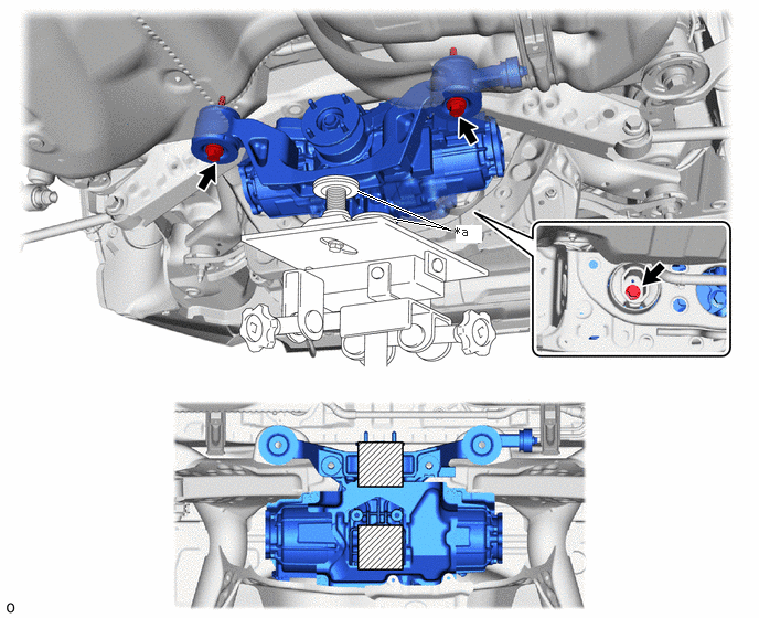
| *a | Attachment | - | - |

|
Attachment Installation Position | - | - |
- CAUTION:
-
The torque vectoring differential carrier assembly is a heavy component. Make sure that it is supported securely.
- NOTICE:
- ·
Use attachments or equivalent tools to keep the torque vectoring differential carrier assembly level.
·Be careful not to damage the frame wire.
Remove the 3 bolts and 2 rear lower differential mount stoppers.
Slowly lower the jack and then tilt the torque vectoring differential carrier assembly.
82164
21.REMOVE FRAME WIRE
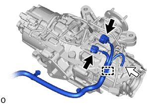
Disconnect the 2 connectors and breather tube.
Disengage the clamp to remove the frame wire.
52380C
22.REMOVE REAR NO. 2 DIFFERENTIAL SUPPORT
Remove the 2 upper rear differential mount stoppers from the rear No. 2 differential support.
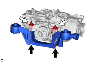
Remove the 2 bolts, 2 nuts and rear No. 2 differential support from the torque vectoring differential carrier assembly.
12351F
23.REMOVE REAR DIFFERENTIAL DAMPER
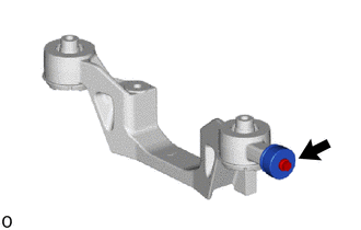
Remove the bolt and rear differential damper from the rear No. 2 differential support.
52391A
24.REMOVE REAR DIFFERENTIAL SUPPORT
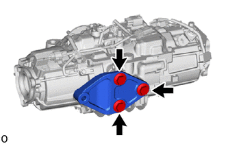
Remove the 3 bolts and rear differential support from the torque vectoring differential carrier assembly.