DRIVE SHAFT / PROPELLER SHAFT PROPELLER SHAFT ASSEMBLY REMOVAL
PROCEDURE

 17410
1.REMOVE FRONT EXHAUST PIPE ASSEMBLY
17410
1.REMOVE FRONT EXHAUST PIPE ASSEMBLY
58152A
2.REMOVE LOWER NO. 1 FRONT FLOOR HEAT INSULATOR
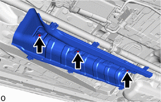
Remove the 3 nuts and lower No. 1 front floor heat insulator.
37100
3.REMOVE PROPELLER SHAFT WITH CENTER BEARING ASSEMBLY
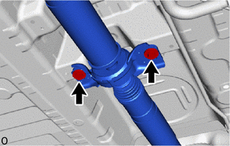
Remove the 2 bolts and 2 center No. 2 support bearing washers, and disconnect the propeller shaft with center bearing assembly.
- NOTICE:
- ·
During the removal, do not exert excessive force on the universal joint.
·When removing, transporting or storing the propeller shaft with center bearing assembly, do not allow the No. 2 joint angle to exceed 20°.
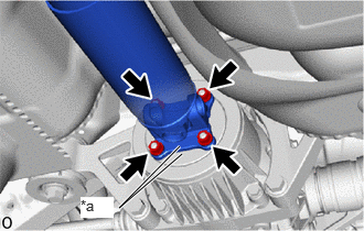
| *a | Matchmark |
Place matchmarks on the differential carrier assembly and propeller shaft with center bearing assembly.
Remove the 4 nuts and 4 washers, and disconnect the propeller shaft with center bearing assembly from the differential carrier assembly.

| *a | Matchmark |
Place matchmarks on the transfer assembly and propeller shaft with center bearing assembly.
Remove the 4 nuts and 4 washers, and disconnect the propeller shaft with center bearing assembly from the transfer assembly.