BRAKE CONTROL / DYNAMIC CONTROL SYSTEMS BRAKE ACTUATOR(for Gasoline Model) REMOVAL
CAUTION / NOTICE / HINT
The necessary procedures (adjustment, calibration, initialization or registration) that must be performed after parts are removed and installed, or replaced during brake actuator assembly removal/installation are shown below.
| Replaced Part or Performed Procedure | Necessary Procedure | Effect/Inoperative Function when Necessary Procedure not Performed | Link |
|---|---|---|---|
| Battery terminal is disconnected/reconnected | Reset back door close position | Power Back Door System | ( 202111,999999,_59,_111831,_0505274,RM100000001ZMEG,) 202111,999999,_59,_111831,_0505274,RM100000001ZMEG,)
|
| Replacement of brake actuator assembly | Update ECU security key | Vehicle Control History (RoB) are stored | (202111,999999,_V1,_111780,_0504977,RM100000001ZKRX,)
|
| Perform "Calibration" | ·
DTCs are stored ·
ABS warning light illuminates ·
Slip indicator light illuminates ·
Electronically controlled brake system does not operate correctly |
(202203,999999,_54,_111814,_0500728,RM1000000022HI0,)
|
|
| Operate the electric parking brake switch | Electric Parking Brake System | (202111,999999,_54,_111818,_0501134,RM100000001Z523,)
|
- HINT:
-
When the cable is disconnected / reconnected to the battery terminal, systems temporarily stop operating. However, each system has a function that completes learning the first time the systems is used.
Items for which learning is completed by driving the vehicle Effect/Inoperative Function when Necessary Procedure not Performed Necessary Procedure Link Lane Tracing Assist System Drive the vehicle straight ahead at 15 km/h (10 mph) or more for 1 seconds or more. ( 202111,999999,_95,_111850,_0502173,RM100000001Z92I,)
Pre-collision System Stop and Start System Idle the engine for approximately 5 to 60 minutes or drive the vehicle until stop and start control is permitted ( 202406,999999,_51,_111803,_0509671,RM100000002KOGF,)
Items for which learning is completed by operating the vehicle normally Effect/Inoperative Function when Necessary Procedure not Performed Necessary Procedure Link Power Door Lock Control System
·Back door opener
Perform door unlock operation with door control switch or electrical key transmitter sub-assembly switch. ( 202111,999999,_58,_111830,_0505351,RM100000001ZMT3,)
Air Conditioning System After the ignition switch is turned to ON, the servo motor standard position is recognized. -
PROCEDURE

 1. PRECAUTION
- NOTICE:
-
After the ignition switch is turned off, there may be a waiting time before disconnecting the negative (-) auxiliary battery terminal.
2.DISCONNECT CABLE FROM NEGATIVE AUXILIARY BATTERY TERMINAL
3.REMOVE WINDSHIELD WIPER MOTOR AND LINK ASSEMBLY
55752
4.REMOVE COWL VENTILATOR SPLASH SHIELD
55704B
5.REMOVE COWL VENTILATOR PANEL SUB-ASSEMBLY
6.DRAIN BRAKE FLUID
- NOTICE:
-
If brake fluid leaks onto any painted surface, immediately wash it off.
82111
7.REMOVE ENGINE ROOM MAIN WIRE
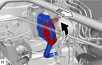

|
Release the lock lever |

|
Disconnect the connector |
Release the lock lever and disconnect the connector from the brake actuator assembly.
- NOTICE:
-
Be careful not to allow any brake fluid to enter the connector.
8.DISCONNECT BRAKE LINE
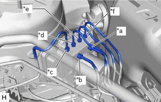
| *a | From 1st Chamber of Brake Master Cylinder Sub-assembly |
| *b | From 2nd Chamber of Brake Master Cylinder Sub-assembly |
| *c | To Front Disc Brake Cylinder Assembly RH |
| *d | To Rear Disc Brake Cylinder Assembly LH |
| *e | To Rear Disc Brake Cylinder Assembly RH |
| *f | To Front Disc Brake Cylinder Assembly LH |
Use tags or make a memo to identify the places to reconnect the brake lines.
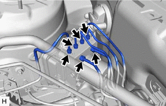
Using a union nut wrench, disconnect the 6 brake lines from the brake actuator assembly.
- NOTICE:
- ·
Do not kink or damage the brake lines.
·Do not allow any foreign matter such as dirt or dust to enter the brake lines from the connecting parts.
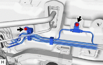
Remove the 2 bolts to separate the brake lines.
9.REMOVE BRAKE ACTUATOR WITH BRACKET
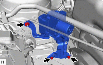
Remove the 2 bolts, nut and brake actuator with bracket.
- NOTICE:
- ·
Do not kink or damage the brake lines.
·Do not allow any foreign matter such as dirt or dust to enter the brake lines from the connecting parts.
·Be careful not to allow any brake fluid to enter the connector.
·Hold the brake actuator with bracket by the brake actuator bracket assembly.
- HINT:
-
Remove the brake actuator with bracket while avoiding the brake lines.
44510
10.REMOVE BRAKE ACTUATOR ASSEMBLY
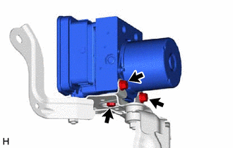
Remove the 3 bolts and brake actuator assembly from the brake actuator bracket assembly.
- NOTICE:
-
Do not hold the brake actuator assembly by the connector.
44521A
11.REMOVE NO. 1 BRAKE ACTUATOR CASE COLLAR
- HINT:
-
Perform this procedure only when replacement of the No. 1 brake actuator case collars is necessary.
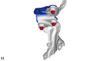
Remove the 3 nuts and upper brake actuator bracket.
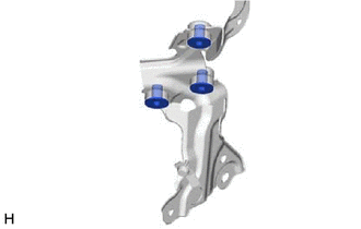
Remove the 3 No. 1 brake actuator case collars from the brake actuator bracket cushion.
44547B
12.REMOVE BRAKE ACTUATOR BRACKET CUSHION
- HINT:
-
Perform this procedure only when replacement of the brake actuator bracket cushions is necessary.
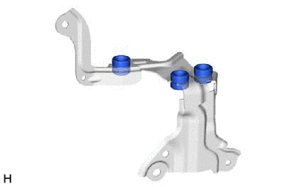
Remove the 3 brake actuator bracket cushions from the lower brake actuator bracket.