PARK ASSIST / MONITORING PARKING SUPPORT BRAKE SYSTEM CALIBRATION
- NOTICE:
-
When any of the following parts have been replaced, perform adjustment shown in the following table. If not, the parking support brake system may not operate correctly.
PRECAUTION (PROCEDURE 1)
The necessary procedures (adjustment, calibration, initialization or registration) that must be performed after parts are removed and installed, or replaced during parking support brake system removal/installation are shown below.
For the installation location of the ultrasonic sensors, refer to Parts Location.
| Part Name | Operation | Adjustment Item | Proceed to |
|---|---|---|---|
| Suspension, tires, etc. | The vehicle height changes because of suspension or tire replacement | Measurement of ultrasonic sensor detection angle | Procedure 2, 3 |
| Ultrasonic sensor detection angle registration | Procedure 4 | ||
| Front bumper assembly | ·
Replacement ·
Installation position of the front bumper assembly changes because of the removal and installation of the front bumper assembly |
Measurement of ultrasonic sensor detection angle | Procedure 2, 3 |
| Ultrasonic sensor detection angle registration | Procedure 4 | ||
| Rear bumper assembly | ·
Replacement ·
Installation position of the rear bumper assembly changes because of the removal and installation of the rear bumper assembly |
Measurement of ultrasonic sensor detection angle | Procedure 2, 3 |
| Ultrasonic sensor detection angle registration | Procedure 4 | ||
| Clearance warning ECU assembly | Replacement | Update ECU security key | ( 202111,999999,_V1,_111780,_0504977,RM100000001ZKRX,) 202111,999999,_V1,_111780,_0504977,RM100000001ZKRX,)
|
| Measurement of ultrasonic sensor detection angle | Procedure 2, 3 | ||
| Bumper type registration | Procedure 4 | ||
| Ultrasonic sensor detection angle registration | |||
| Ultrasonic sensor | ·
Removal and installation ·
Replacement |
Measurement of ultrasonic sensor detection angle | Procedure 2, 3 |
| Ultrasonic sensor detection angle registration | Procedure 4 | ||
| An ultrasonic sensor becomes misaligned | Measurement of ultrasonic sensor detection angle | Procedure 2, 3 | |
| Ultrasonic sensor detection angle registration | Procedure 4 | ||
| An ultrasonic sensor is subjected to impact | Measurement of ultrasonic sensor detection angle | Procedure 2, 3 | |
| Ultrasonic sensor detection angle registration | Procedure 4 | ||
| Blind spot monitor system* | Replacement | Blind spot monitor beam axis confirmation | (202111,999999,_56,_111825,_0500531,RM100000001Z2RP,)
|
*: w/ Blind Spot Monitor System
PREPARATION (PROCEDURE 2)
Preparation
Digital angle gauge
Digital angle gauge attachment
Masking tape (To prevent damage)
A level
- SST
- 09989-00020
Confirm levelness of floor surface.
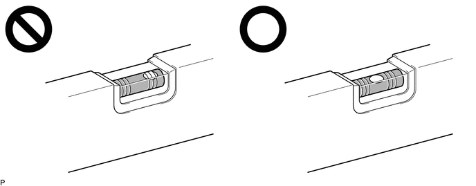
Place a bubble level on a level surface and confirm that the bubble is centered.
- NOTICE:
-
Make sure that there is no gravel, sand, etc., and that the surface is not undulating.
- HINT:
-
By adjusting the direction of the bubble level, it is possible to find a position where the bubble is centered.
Turn on the digital angle gauge.
Place the digital angle gauge in the same location and direction as that of the bubble level where the levelness of the surface was confirmed.
- NOTICE:
-
Confirm that the location and direction of the digital angle gauge is exactly the same as that of the bubble level.
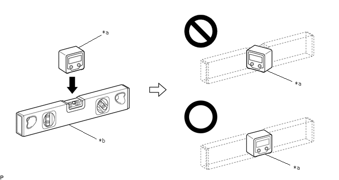
| *a | Digital Angle Gauge | *b | Level |
Press the "ZERO" switch to memorize the zero point (perfectly level).
- NOTICE:
-
Make sure that the digital angle gauge does not move when pressing the switch. If the digital angle gauge moves when the switch is pressed, an incorrect zero point may be memorized and it will not be possible to accurately check for levelness.
Using the digital angle meter in which the zero point (perfectly level) has been memorized, measure the angle of the floor surface at the 4 positions at the front of the vehicle and the 4 positions at the rear of the vehicle as shown in the illustration. Write the measured values into the following worksheet.
- NOTICE:
- ·
Always position the digital angle gauge as shown in the illustration.
·Make sure that there is no gravel, sand, etc., and that the floor surface is not undulating.
·When measuring the angle of the floor surface, avoid uneven areas such as joints between tiles.
- HINT:
-
If necessary, the digital angle gauge can be placed anywhere within the specific area when measuring the angle of the floor surface for positions A, C, F and H.
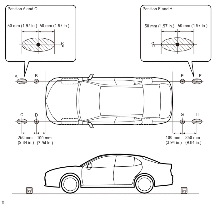

|
Confirmation Area | - | - |
Using the following worksheet, calculate the average of the measurements taken at the 4 positions in front of the vehicle, and calculate the average of the measurements taken at the 4 positions behind the vehicle. Confirm that the front measurement average and the rear measurement average are not more than approximately 0.37 degrees. Also, confirm that the front measurement average and the rear measurement average is less than 0.2 degrees.
- NOTICE:
-
If the front measurement average and the rear measurement average are more than approximately 0.37 degrees or the difference between the front measurement average and the rear measurement average is 0.2 degrees or more, choose another work area as it is not possible to accurately check the installation angle of the sensors.
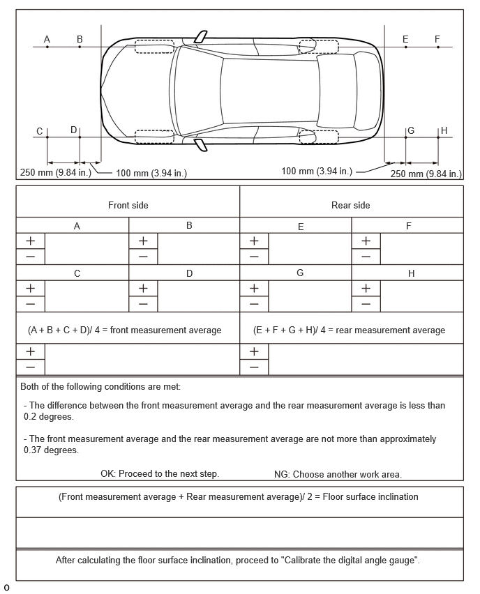
Average the front measurement average and the rear measurement average, then round the answer to 1 decimal place (E.g. 0.0927 degrees is rounded to 0.1 degrees) to obtain the floor surface inclination value.
Calibrate the digital angle gauge
Adjust the angle of the digital angle gauge until it reads the same value of the floor surface inclination, then press the "ZERO" switch to memorize the zero point (level with floor surface).
- NOTICE:
-
Before pressing the "ZERO" switch, confirm that the digital angle gauge reading is positive if the floor angle inclination is positive, and negative if the floor angle inclination is negative.
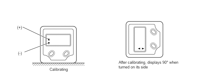
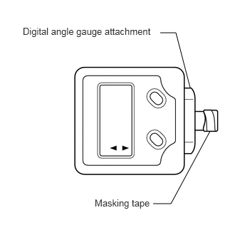
Prepare the digital angle gauge
Attach the digital angle gauge attachment to the digital angle gauge.
- SST
- 09989-00020
Attach masking tape to the digital angle gauge attachment.
Remove all luggage from the vehicle.
Adjust the tire inflation pressure to the specified pressure.
Click hereGeneral>MAINTENANCE>TIRE AND WHEEL>INSPECTION202111,999999,_V1,_112220,_0502516,RM100000001ZAD4,
Check the height of the vehicle.
SENSOR HEIGHT AND ALIGNMENT INSPECTION (PROCEDURE 3)
- HINT:
-
Check if the installation angle of each ultrasonic sensor is appropriate.
Preparation
Visually check that the bumper, grill and ultrasonic sensors are installed properly and are not damaged.
- NOTICE:
-
If the bumper, grill or any ultrasonic sensor is not installed correctly, the calibration may not be able to be completed.
Check the tire pressures and adjust them if necessary.
Click hereGeneral>MAINTENANCE>TIRE AND WHEEL>INSPECTION202111,999999,_V1,_112220,_0502516,RM100000001ZAD4,
- NOTICE:
- ·
Ensure that the vehicle is level in an area with no wind.
·Do not lean on the vehicle.
·Do not do anything that may affect the level of the vehicle during the calibration, such as getting in or out of the vehicle, or adding or removing luggage.
Sensor height and alignment inspection
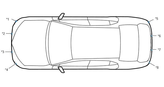
| *1 | Front Corner Ultrasonic Sensor RH | *2 | Front Center Ultrasonic Sensor RH |
| *3 | Front Center Ultrasonic Sensor LH | *4 | Front Corner Ultrasonic Sensor LH |
| *5 | Rear Corner Ultrasonic Sensor RH | *6 | Rear Center Ultrasonic Sensor RH |
| *7 | Rear Center Ultrasonic Sensor LH | *8 | Rear Corner Ultrasonic Sensor LH |
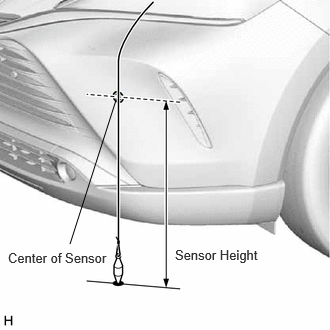
Measure the installation height of the sensors.
- Standard Height (Front Bumper) (for SFTM Made):
Sensor Location Sensor Height Front Center Ultrasonic Sensor 594.8 to 651.4 mm (23.4 to 25.6 in.) Front Corner Ultrasonic Sensor 607.3 to 663.3 mm (23.9 to 26.1 in.)
- Standard Height (Front Bumper) (for GTMC Made):
Sensor Location Sensor Height Front Center Ultrasonic Sensor 556.0 to 612.5 mm (21.9 to 24.1 in.) Front Corner Ultrasonic Sensor 592.4 to 648.4 mm (23.3 to 25.5 in.)
- Standard Height (Rear Bumper):
Sensor Location Sensor Height Rear Center Ultrasonic Sensor 653.9 to 706.4 mm (25.7 to 27.8 in.) Rear Corner Ultrasonic Sensor 651.6 to 703.9 mm (25.7 to 27.7 in.)
- NOTICE:
-
If the installation height of a sensor is not as specified, it may not be possible to measure the sensor angles correctly. If so, unload the vehicle and measure the installation height of the sensors again.
- HINT:
-
Use the center of the sensor as the measuring point.
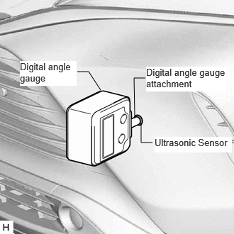
Using the digital angle gauge, measure the angles of each sensor. Write down the measured values.
Measure the angle of the front sensors as shown in the illustration.
- NOTICE:
-
Ensure that the digital angle gauge is flush with the face of the sensor.
Measure the angle of the rear sensors.
- NOTICE:
-
Ensure that the digital angle gauge is flush with the face of the sensor.
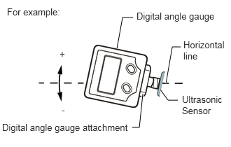
Confirm that the angles of the sensors are as specified.
- NOTICE:
-
The sensor angle is the measured sensor angle subtracted from 90°.
- HINT:
- ·
The digital angle gauge should indicate 90° when turned on its side.
·If the face of the sensor is tilted upwards, the sensor angle will be positive.
- Standard Angle (Front Bumper) (for SFTM Made):
Sensor Location Installation Angle Front Center Ultrasonic Sensor -5.0 to 3.1° Front Corner Ultrasonic Sensor 1.9 to 10.0°
- Standard Angle (Rear Bumper) (for SFTM Made):
Sensor Location Installation Angle Rear Center Ultrasonic Sensor 0.2 to 8.3° Rear Corner Ultrasonic Sensor -2.7 to 5.4°
- Standard Angle (Front Bumper) (for GTMC Made):
Sensor Location Installation Angle Front Center Ultrasonic Sensor -4.8 to 3.4° Front Corner Ultrasonic Sensor 3.1 to 11.3°
- Standard Angle (Rear Bumper) (for GTMC Made):
Sensor Location Installation Angle Rear Center Ultrasonic Sensor 0.1 to 8.3° Rear Corner Ultrasonic Sensor -2.8 to 5.4°
If the angle or height of the sensors is not as specified, confirm that the installation is correct and then perform troubleshooting again.
REGISTRATION (PROCEDURE 4)
Preparation
Confirm that the following DTCs are not output.
| System | Proceed to |
|---|---|
| Toyota Parking Assist-sensor System | (202111,999999,_56,_111825,_0501856,RM100000001Z7UT,)
|
| Parking Support Brake System | (202111,999999,_56,_111825,_0501857,RM100000001Z7VS,)
|
- NOTICE:
-
If DTC C1AE187/C1AE287/C1AE387/C1AE487/C1AE687/C1AE787/C1AE887 or C1AE987 are output at this point, it is not due to a malfunction. Proceed with the calibration.
Connect the GTS to the DLC3.
Turn the ignition switch to ON.
Turn the GTS on.
Enter the following menus: Body Electrical / Clearance Warning / Utility.
- Body Electrical > Clearance Warning > Utility
-
Tester Display ECU Calibration - 50005 438 2535
According to the display on the GTS, perform calibration.
- HINT:
-
If "Battery or Steering Sensor" is selected, further calibration is not required. (Bumper type registration is not required.)
Enter the bumper type using the GTS.
| Bumper Type | Value |
|---|---|
| Standard | 1 |
- HINT:
-
If the clearance warning ECU assembly is replaced or removed and installed, it is necessary to perform bumper type registration.
Using the GTS, enter the measured sensor values.
- NOTICE:
-
The sensor angle is the measured sensor angle subtracted from 90°.
- HINT:
-
The digital angle gauge should indicate 90° when turned on its side.
Disconnect the GTS from the DLC3.